
Setup Guide Instruction Manual

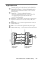
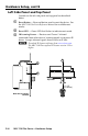
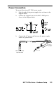
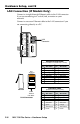
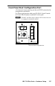
Table Of Contents
- Front cover
- Safety Precautions
- Safety Precautions (Chinese) and FCC Class A Notice
- Table of Contents
- Ch. 1: Introduction
- Ch. 2: Hardware Setup
- Ch. 3: Software Setup
- Creating a Global Configurator Project File
- Configuring a New Device
- Step six: configure e‑mail server (IP models only)
- Step seven: configure e‑mail messages (IP models only)
- Step eight: configure contacts (IP models only)
- Step nine: assign serial device drivers
- Step ten: assign IR drivers
- Step eleven: configure the front panel
- Step twelve: configure associated control modules
- Step thirteen: create a shutdown schedule
- Step fourteen: create a lamp hour notification (IP models only)
- Step fifteen: create a disconnect notification (IP models only)
- Step sixteen: build the Global Configurator file
- Step seventeen: upload the Global Configurator file
- Step eighteen: launch GlobalViewer (IP models only)
- Testing the GlobalViewer pages
- Warranty
- Back cover:checklist and contact information
MLC 104 Plus Series • Hardware Setup
Hardware Setup, cont’d
2-8
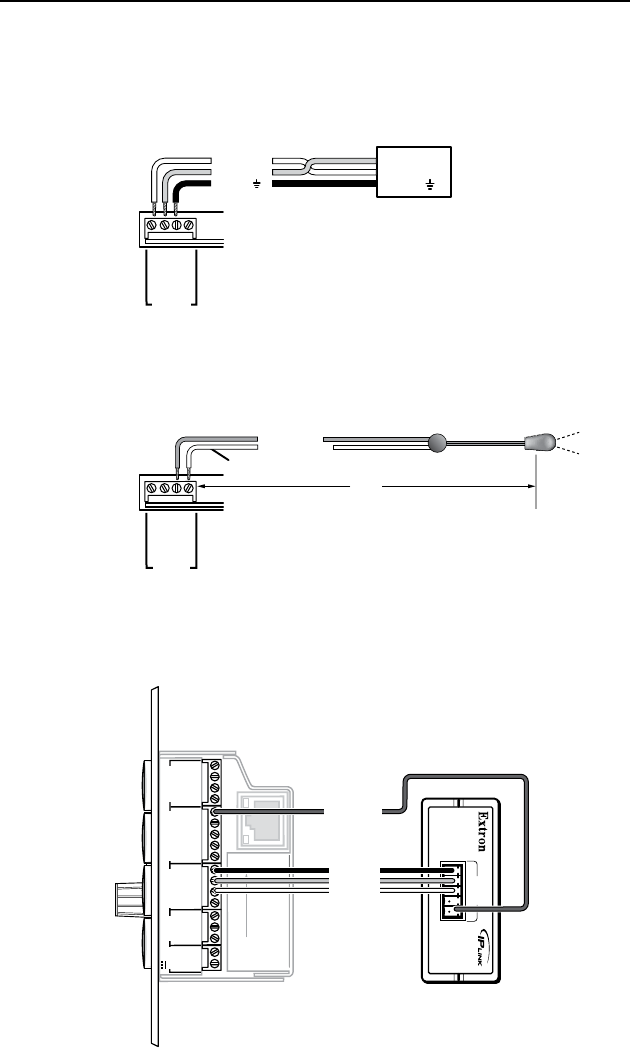
Device Connections
The following illustrations show examples of A/V and control
device connections for all models.
Display connection
Projector
Panel
MLC 104 Plus Series
Right Side Panel
DISPLAY
RS-232/IR
GROUND
IR OUT
Tx
Rx
Ground ( )
Receive (Rx)
Tr ansmit (Tx)
Ground ( )
Receive (Rx)
Tr ansmit (Tx)
Bidirectional
Infrared (IR) connection
MLC 104 Plus Series
Right Side Panel
DISPLAY
RS-232/IR
GROUND
IR OUT
Tx
Rx
G = Ground
IR Emitter 1
White Striped Wire
100'
(30.5 m)
S = Signal (IR)
Digital I/O connection
MLC 104 Plus Series
Right Side
IPA T RLY4
Front Panel
1
2
3
GROUND
+12V OUT
CM
GROUND
IR OUT
GROUND
SCP
GROUND
Tx
Rx
DISPLAY
RS-232/IR
A B C D E
COMM LINK
LAN
PRESS TAB WITH
TWEEKER TO REMOVE
A B
MLS
RS-232
POWER
12V
DIGITAL
I/O
IR IN
Tx
GROUND
Rx
+12V IN
IPA T RLY4
1 2 3 4 C
INPUTS
Relay 1
Relay 2
Relay 3
+12 VDC