
Setup Guide Instruction Manual

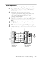
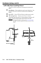
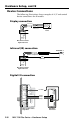
Table Of Contents
- Front cover
- Safety Precautions
- Safety Precautions (Chinese) and FCC Class A Notice
- Table of Contents
- Ch. 1: Introduction
- Ch. 2: Hardware Setup
- Ch. 3: Software Setup
- Creating a Global Configurator Project File
- Configuring a New Device
- Step six: configure e‑mail server (IP models only)
- Step seven: configure e‑mail messages (IP models only)
- Step eight: configure contacts (IP models only)
- Step nine: assign serial device drivers
- Step ten: assign IR drivers
- Step eleven: configure the front panel
- Step twelve: configure associated control modules
- Step thirteen: create a shutdown schedule
- Step fourteen: create a lamp hour notification (IP models only)
- Step fifteen: create a disconnect notification (IP models only)
- Step sixteen: build the Global Configurator file
- Step seventeen: upload the Global Configurator file
- Step eighteen: launch GlobalViewer (IP models only)
- Testing the GlobalViewer pages
- Warranty
- Back cover:checklist and contact information
MLC 104 Plus Series • Hardware Setup
2-3
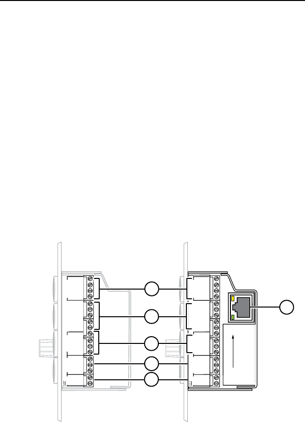
Right Side Panel
Connectors on the unit's right side panel are described below.
a
Display RS-232 / IR port — Dedicated bidirectional port for
communication to a projector or display via RS-232 and/or
infrared control.
b
Comm Link — This port can be used to connect
• up to four control modules (IRCMs, ACMs, RCMs, CMs)
• one Extron IR signal repeater (IRL 20 or IR Link)
• two SCP 104 control panels
c
Digital I/O — Congurable as a digital input or digital output
to connect to devices such as sensors, switches, LEDs, and
relays.
d
MLS RS-232 — Use to control an optional Extron switcher, or
other RS-232 device.
e
PWR — Use to connect the supplied 12 VDC power supply.
f
LAN (IP models only) — Use to connect to a local area network.
2
3
GROUND
1
IR IN
GROUND
IR OUT
CM
SCP
GROUND
GROUND
Tx
Rx
DISPLAY
RS-232/IR
LAN
PRESS TAB WITH
TWEEKER TO REMOVE
A B
MLS PWR
RS-232 12V
DIGITAL
I/O
A B C D E
COMM LINK
+V OUT
GROUND
Tx
Rx
+12V IN
MLC 104 IP Plus
Right Side
MLC 104 Plus
Right Side
2
3
GROUND
1
IR IN
GROUND
IR OUT
CM
SCP
GROUND
GROUND
Tx
Rx
DISPLAY
RS-232/IR
A B
MLS PWR
RS-232 12V
DIGITAL
I/O
A B C D E
COMM LINK
+V OUT
GROUND
Tx
Rx
+12V IN
6
*Available on
IP models
only
4
5
3
2
1