
User guide


Table Of Contents
6. Connect a power supply (see page 11).
ATTENTION: Read the attention points on page 11 before connecting the
power supply.
If the MLA VC10 Plus is being used with Extron MLC or IP Link control processors, the
units can share a power supply (see the wiring diagram shown on page 12). If the
volume control module is used with any other control device, it requires a separate
12 VDC power supply. Extron provides a 12 VDC, 1 A power supply (part number
70-775-01), which must be purchased separately.
Connections for Volume Control
The MLA VC10 Plus controls the remote volume control port of an amplier. All Extron
MPA and half-rack XPA amplifiers and most third-party models can be controlled by a
potentiometer, which is the default setting for the MLA VC10 Plus. Other third-party
amplifiers may require a variable DC voltage signal to control the audio volume.
Consult the user guide for the amplifier to find out the specific requirements of your
equipment before connecting it to the MLA VC10 Plus. Additionally, the audio can be
muted by connecting the captive screw relay connections to the contact closure mute
terminals of the amplifier, if they are available.
Volume Control by Potentiometer
The following examples show how to wire the resistance control terminals of the
MLA VC10 Plus to the Extron MPA and half-rack XPA ampliers, or some common
third-party amplifiers.
When using three-pin potentiometer control, RS-232 commands control the variable
resistance across the signal (wiper) pin (C) to the ground pin (G). Across the reference (V)
and ground (G) will always be xed at 10 kilohm. Other controllers and ampliers not
shown here require similar connections, but you must read the appropriate user guides to
ensure the wiring is correct.
Extron Amplier
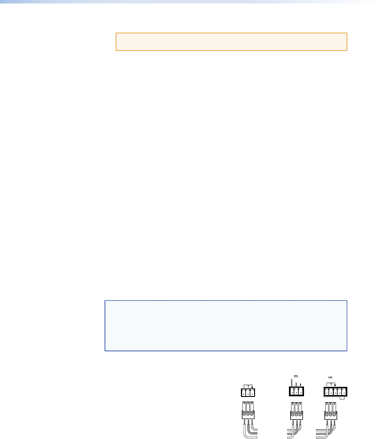
This example shows how to connect the MLA VC10 Plus to an Extron amplier. All Extron
amplifiers can be controlled by a potentiometer, using three pins.
NOTES: • By default, the MLA VC10 Plus control mode is set to potentiomenter and
the maximum resistance output range is set to 10 kilohm. These are the
settings required by all Extron amplifiers.
• Volume control pins may be labeled as V, C, and G (see the half-rack
XPA Series Amplifier) or 10V, Vol/Mute, and G (see the MPA Amplifier). The
wiring and function are the same, whichever way your product is labeled.
1. If necessary, use SIS commands to set
the control mode (see page 35) to
potentiometer and set the maximum
potentiometer output range (see
page 35).
2. Connect the reference voltage pin (V) from
the MLA VC10 Plus to the reference voltage
terminal (10V on the MPA; V on the XPA).
Ground
Reference
Control (variable)
G
C
V
G
C
V
Extron
MLA VC10 Plus
REMOTE
VOL/MUTE
10V 50mA
Extron MPA
Amplifier
R
GVC
Extron
Half-rack
XPA Series
Amplifier
10V 50mA
GVC
G
STANDBY
OR
MLA VC10 Plus • Installation and Cabling 6