
User Guide Owner's manual
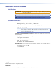

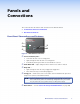
Table Of Contents
Panels and
Connections
This section describes the features and connectors for the MLA VC10 Plus:
z Front Panel Connections and Features
z Rear Panel Connections
Front Panel Connections and Features
CONFIG
RELAY
MUTE
MLA VC10 Plus
R
a
b
c
e
d
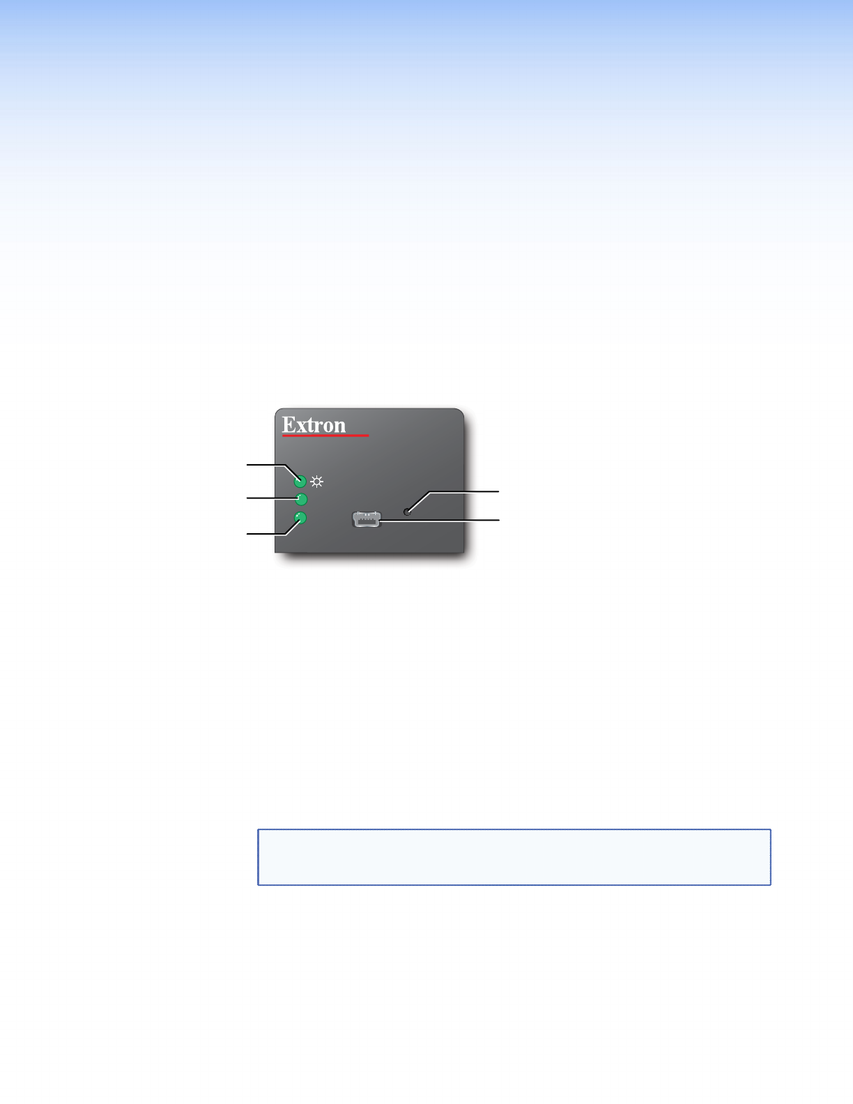
Figure 2. MLA VC10 Plus Front Panel
a Power and Activity LED —
z Is off when the unit is not receiving power
z Lights solid green when the unit is receiving power
z Continuously flashes green while SIS commands are received.
b Audio Mute LED — lights solid green when volume level is at 0 or is muted.
c Relay LED —
z Lights solid green when the relay is triggered or toggled on.
z Pulses when the relay is momentarily triggered
d Config port — A USB cable can be connected to this mini B USB female port when
using a PC to connect to the MLA VC10 Plus.
NOTE: During configuration, the host PC provides power through the USB cable.
This is sufficient to power the unit during configuration only. For normal
use, the unit must receive power from a 12 VDC power supply.
e Reset Button — used to reset to the factory-installed firmware (see page 19).
MLA VC10 Plus • Panels and Connections 3