
User Guide Owner's manual
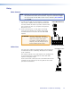
Table Of Contents

z The ground line may be noisy. Use a different, “clean” grounding source. The chassis
of the MediaLink controller (if used), the power supply, the MLA VC10 Plus, and the
amplifier or mixer should all share a common ground.
The audio output can still be heard when the MLA VC10 Plus has a volume setting
of 0 VDC
z Check the gain and level settings on the amplifier or mixer. Adjust the gain so that you
do not hear any audio output when the MLA VC10 Plus is set for minimum volume.
z The variable voltage or resistance ports on the MLA VC10 Plus do not always reach
the absolute minimum or maximum. Therefore, if the audio amplifier has remote mute
capability, use the contact closure relay switches on the MLA VC10 Plus.
NOTE: Some amplifiers do not obtain good maximum or minimum volume
control through their remote volume terminals.
The volume does not change when you change the volume setting via the MLC or
via the RS-232 commands:
z Check Power and Activity LED (a in figure 2) — it blinks green when commands
are received.
z Ensure the front panel USB connection is removed and recycle power to the 12 VDC
port only (a in the rear panel diagram on page 4).
z The wiring at the amplifier or mixer terminals may be incorrect.
z Check that RS-232 settings are 9600 bps, 8 data bits, 1 stop bit, no parity.
z Check that the correct control mode (voltage or potentiometer) has been set on
the MLA VC10 Plus (see page 35). Only one port can be active at a time.
z The maximum output voltage or resistance may be set incorrectly. Retest the control
voltage of the amplifier or check the user guide for the amplifier to verify the
maximum voltage. Reset the maximum output voltage or resistance as required
(see page 35).
z The amplier may accept a higher control voltage than the MLA VC10 Plus provides,
so the amplifier will not reach its highest volume level.
z Test the equipment with another amplifier.
The volume level from the amplifier changes in the opposite direction to the knob
on the controller.
z Check the wiring to ensure that the pins for resistance or voltage control are
connected appropriately (see page 6 if using resistance or page 8 if using voltage).
z Check the user guide of the amplifier to see whether it should be controlled by
inverse mode. If so, use SIS commands to enable or disable inverse mode on the
MLA VC10 Plus (see page 35).
There is no voltage or resistance change or no output from the MLA VC10 Plus
control ports.
z Ensure the front panel USB connection is removed. Shut off the device and reapply
power to the 12 VDC port only (f in the rear panel diagram on page 4).
z Check that the correct control mode (voltage or potentiometer) has been set on
the MLA VC10 Plus (see page 35). Only one port can be active at a time.
If you have other problems, or for further advice, contact the Extron support staff (see
the contact information on the back page of this user guide).
MLA VC10 Plus • Operation 24