
User Guide Owner's manual
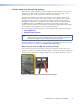
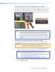
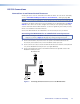
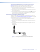
Table Of Contents
Volume Control by Variable DC Voltage
When volume is being controlled by variable voltage, serial SIS commands sent from the
controller to the MLA VC10 Plus control the voltage output across the signal (+) and
ground (G) pins. This in turn, controls the audio level of the amplier.
Consult the user guide for the amplifier to find out the specific requirements of your
equipment before connecting it to the MLA VC10 Plus. If the amplier requires variable
DC voltage control, you will need to find out the maximum control voltage, to avoid
damaging the equipment. The user guide for the amplifier may list the required voltage.
The table that starts on page 28 shows the voltage requirements of many common
ampliers. However, Extron recommends that you conrm the voltage yourself by reading
the user guide for the amplifier or, if necessary, using a voltmeter.
This section describes how to measure the control voltage for two widely -used amplifiers.
z Peavey UMA 35T II
z Biamp Precedence CMA 60
NOTE: The MLA VC10 Plus is compatible with a wide range of amplifiers. The models
shown in this section are included as examples only. The MLA VC10 Plus is not
limited to working with only the amplifiers shown in this guide.
After describing how to measure the control voltage, the guide describes how to connect
the MLA VC10 Plus to an amplier for volume control by voltage.
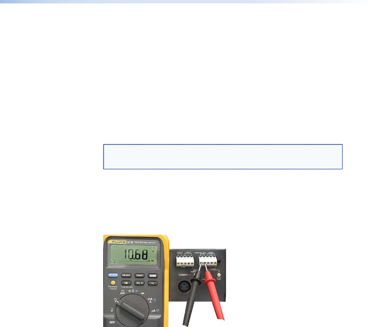
Measuring the Peavey UMA 35T II control voltage
In the example shown below, the voltage control pins are labeled “Remote Vol.” Use a
voltmeter, set to VDC, to measure the voltage. Make a record of the measured voltage and
which terminal is ground. If the voltage is negative the meter probes need to be reversed.
Figure 4. Measuring the Peavey UMA 35T II Control Voltage
MLA VC10 Plus • Installation and Cabling 8