
User Guide Owner's manual
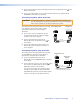
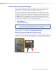
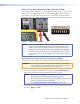
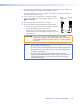
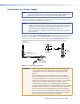
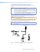
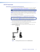
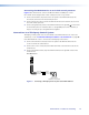
Table Of Contents
3. Connect the ground pin (G) from the MLA VC10 Plus to the ground terminal ( on the
MPA; G on the XPA).
4. Connect the signal (wiper) pin (C) from the MLA VC10 Plus to the signal terminal
(VOL/MUTE on the MPA; C on the XPA).
Third-party amplier (three terminals)
ATTENTION: For third-party amplifiers, consult the user guide for the amplifier to see
how the manufacturer has labeled the different connectors and whether
two or three terminals are used for potentiometer control.
This example shows the MLA VC10 Plus connected
to an Ashly NE series amplier, which requires
a maximum potentiometer output range of
10 kilohms.
1. Connect the reference voltage pin (V) from
the MLA VC10 Plus to the reference voltage
terminal (+5V) on the amplier.
2. Connect the ground wire (G) from the
MLA VC10 Plus to the ground terminal ( ) on
the amplifier.
3. Connect the signal (wiper) wire (C) from the
MLA VC10 Plus to the signal terminal (CH 1)
on the amplifier.
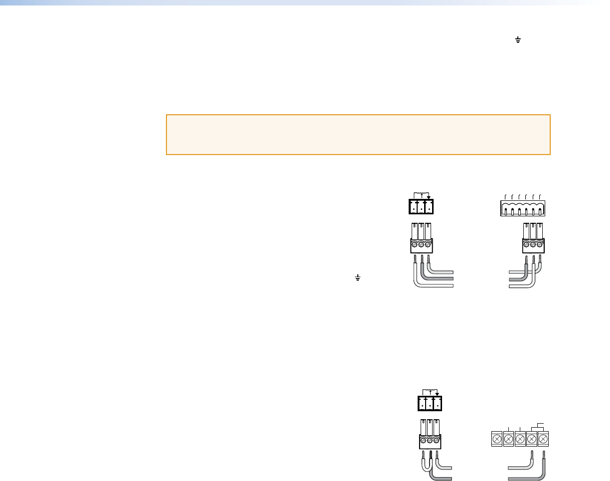
Third-party amplier (two terminals)
This example shows the MLA VC10 Plus connected
to a TOA 900 Series amplifier, which requires a
potentiometer output range of 10 kilohms.
1. Connect the ground wire (G) from the
MLA VC10 Plus to the left REMT VOL terminal on
the amplifier.
2. Connect both the reference wire (V) and the signal
wire (C) from the MLA VC10 Plus to the right
REMT VOL terminal on the amplier.
This can be achieved by connecting the signal
terminal (C) of the MLA VC10 Plus to both the
right REMT VOL terminal on the amplifier and the
reference terminal (V) of the MLA VC10 Plus.
Ground
Reference
Extron MLA VC10 Plus
Ashly NE series
CH 4
CH 3
CH 2
GND
+5V
CH 1
Control (variable)
G
C
V
R
GVC
G Ground
REMT
VOL
MUTE
1
MUTE
2
GND
C Control (variable)
Extron MLA VC10 Plus
TOA 900 Series
Amplifier
Connect the signal (C) and reference (V)
terminals of the MLA VC10 Plus.
Connect the signal (C) terminal to the amplifier.
R
GVC
MLA VC10 Plus • Installation and Cabling 7