User Guide Audio MLA VC10 Plus Volume Control Module 68-1828-01 Rev.
Safety Instructions • English This symbol is intended to alert the user of important operating and maintenance (servicing) instructions in the literature provided with the equipment. This symbol is intended to alert the user of the presence of uninsulated dangerous voltage within the product enclosure that may present a risk of electric shock. Warning Power sources • This equipment should be operated only from the power source indicated on the product.
FCC Class A Notice This equipment has been tested and found to comply with the limits for a Class A digital device, pursuant to part 15 of the FCC rules. The Class A limits provide reasonable protection against harmful interference when the equipment is operated in a commercial environment. This equipment generates, uses, and can radiate radio frequency energy and, if not installed and used in accordance with the instruction manual, may cause harmful interference to radio communications.
Conventions Used in this Guide Notifications ATTENTION: Attention indicates a situation that may damage or destroy the product or associated equipment. NOTE: A note draws attention to important information. TIP: A tip provides a suggestion to make working with the application easier.
Contents Introduction............................................................ 1 Operation............................................................... 20 MLA VC10 Plus Description................................. 1 MLA VC10 Plus Features...................................... 1 Operation.......................................................... 20 Voltage or Resistance Control........................ 20 Inverse Mode.................................................
MLA VC10 Plus • Contents vi
Introduction This user guide contains information about the Extron MLA VC10 Plus volume control module with instructions for experienced installers on how to install, configure, and operate the equipment. Unless otherwise specified, references in this guide to the “MLA” relate to the features or operation of the MLA VC10 Plus. References to the “control processor” or “controller” refer to the Extron or third-party controller that provides RS‑232 commands to the MLA VC10 Plus.
Inverse mode — In normal mode, 0 is mute and 10 VDC or 10 kilohm is the maximum volume. In inverse mode, this reverses the output to 0 (maximum volume) to 10 VDC or 10 kilohm (minimum volume). Relay switch — This switch has a Normally Open (NO) pin and a Normally Closed (NC) pin. This relay can be used to mute audio on an amplifier or mixer.
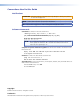
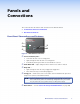
Panels and Connections This section describes the features and connectors for the MLA VC10 Plus: zz Front Panel Connections and Features zz Rear Panel Connections Front Panel Connections and Features MLA VC10 Plus a b MUTE CONFIG R RELAY c Figure 2. a b c d d MLA VC10 Plus Front Panel Power and Activity LED — zz Is off when the unit is not receiving power zz Lights solid green when the unit is receiving power zz Continuously flashes green while SIS commands are received.
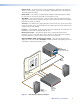
Rear Panel Connections CONTROL OUTPUT RELAY NO C POWER 12V 0.3A MAX REMOTE RS-232 Tx f Figure 3. f Rx g G NC R V-DC G h V C i G j MLA VC10 Plus Rear Panel Power — Connect a 12 VDC power supply to this two pole captive screw connector. The MLA VC10 Plus can be wired to share the power supply with other products (see “Sharing a Power Supply with an Extron Controller” page 12 for more information). The Extron power supply (part number 70‑775‑01) is optional.
Installation and Cabling This section describes zz Installation Overview zz Connections for Volume Control zz Connections to a Power Supply zz RS-232 Connections zz Relay Installation Overview This section provides a brief overview of how to install and set up the MLA VC10 Plus. 1. Decide where the MLA VC10 Plus will be placed and, if necessary, any mounting requirements (see page 37).
6. Connect a power supply (see page 11). ATTENTION: Read the attention points on page 11 before connecting the power supply. If the MLA VC10 Plus is being used with Extron MLC or IP Link control processors, the units can share a power supply (see the wiring diagram shown on page 12). If the volume control module is used with any other control device, it requires a separate 12 VDC power supply. Extron provides a 12 VDC, 1 A power supply (part number 70‑775-01), which must be purchased separately.
3. Connect the ground pin (G) from the MLA VC10 Plus to the ground terminal ( on the MPA; G on the XPA). 4. Connect the signal (wiper) pin (C) from the MLA VC10 Plus to the signal terminal (VOL/MUTE on the MPA; C on the XPA). Third-party amplifier (three terminals) ATTENTION: For third-party amplifiers, consult the user guide for the amplifier to see how the manufacturer has labeled the different connectors and whether two or three terminals are used for potentiometer control.
Volume Control by Variable DC Voltage When volume is being controlled by variable voltage, serial SIS commands sent from the controller to the MLA VC10 Plus control the voltage output across the signal (+) and ground (G) pins. This in turn, controls the audio level of the amplifier. Consult the user guide for the amplifier to find out the specific requirements of your equipment before connecting it to the MLA VC10 Plus.
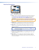
Measuring the Biamp Precedence CMA 60 control voltage Several Biamp amplifiers have three screw terminals labeled “remote level.” The terminals, shown in the inset in figure 5, are reference (+10v), ground ( ), and control voltage (C). Use a voltmeter to measure the voltage between the control terminal and the ground terminal as shown in figure 5. Record the measured voltage and which terminal is ground. Figure 5.
3. Ensure you know the maximum control voltage for your amplifier. In this example, the maximum voltage output range for the amplifier is 10 VDC. For more information, see the user guide for the amplifier or measure the voltage, as described in the previous section. 4. If necessary, use an SIS command to set maximum voltage output. For example, to set the maximum voltage to 7.5 V: EV*7.50VLCM} Extron Amplifier MLA VC10 Plus +10V V-DC GND Vc 5. Disconnect the USB connection to the computer. 6.
Connections to a Power Supply NOTE: During configuration, the host PC provides power through the USB cable. This is sufficient to power the unit during configuration only. During normal operation, the unit must receive power from a 12 VDC power supply. Connect a 12 VDC, power supply to this two pole captive screw connector. Ensure the connections have the correct polarity (see figure 6). NOTES: • The length of the exposed wires in the stripping process is critical. The ideal length is 3/16 inches (5 mm).
Sharing a Power Supply with an Extron Controller The MLA VC10 Plus can share a power supply with any Extron MLC or IP Link control processor. NOTES: • Power cables must be at least 18 AWG. • If the cable has a drain wire, it should be grounded at both ends. To avoid introducing noise and static into audio channels, the chassis of the control processor (if used), the power supply, the MLA VC10 Plus, and the amplifier or mixer should all share a common ground.
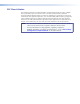
RS-232 Connections Connections to an Extron Control Processor Control processors issue SIS commands to the MLA VC10 Plus. For a list of SIS commands, see the “Command and Response Table for SIS Commands,” starting on page 33. NOTE: For permanent installations, use the RS-232 port, not the front panel USB port. Serial drivers for Extron control processors are available for free download from the Extron website.
Connecting the MLA VC10 Plus to an IP Link control processor Figure 8 also shows how to connect the MLA VC10 Plus to COM port 1 of the IPL T SFI244. Connecting to other IP Link control processors is very similar. 1. Connect the Transmit (Tx) socket on the rear panel of the MLA VC10 Plus to the Receive (Rx) socket of an IP Link control processor. 2. Connect the Receive (Rx) socket of the MLA VC10 Plus to the Transmit (Tx) socket of an IP Link control processor. 3.
Relay Mute Control NOTE: By default, the Auto Mute feature of the MLA VC10 Plus automatically triggers the relay when the volume level reaches 0%. If you use a controller to trigger the relay instead, this Auto Mute feature must be disabled by SIS command (see page 35). 1. Consult the user guide for the amplifier to see whether mute control is available with the amplifier and whether the mute terminals need to be opened or closed for mute to be activated.
Software Control Software is not normally required to operate the MLA VC10 Plus. However, to configure the unit or update the firmware, this section provides essential information.
Activating the USB Port for the First Time NOTE: When DataViewer is installed on your computer, the Extron USB Driver is installed at the same time. This driver is required to connect your computer to any Extron product with a USB port. When the USB connection is made, the Found New Hardware Wizard opens automatically. 1 1 Figure 10. Hardware Wizard — 1 1. Select No, not this time and click Next. The second Hardware Wizard screen opens: 2 2 Figure 11. Hardware Wizard — 2 2.
Configuring the Extron Controller Extron controllers may need be configured to work with the MLA VC10 Plus. The appropriate software ships with the controller. For complete configuration instructions, see the user guide for your Extron controller and the help file for the appropriate software. An MLA VC10 Plus serial driver is available for easy configuration of Extron control processors. Follow these instructions to download the driver. 1.
5. If the version available for download is more recent than the version on your volume control module, click Download and follow the on-screen instructions. The file will be downloaded to your computer. Make a note of the folder where it is saved. NOTE: Upgrading your firmware requires the Extron Firmware Loader software to be installed on the computer. The software is available for free download from the Extron website (see “Software Installation,” on page 18). Installing the Firmware 1.
Operation This section of the guide describes zz Operation zz Troubleshooting Operation The Extron MLA VC10 Plus Volume Control Module converts RS-232 commands from a control system into voltage or impedance changes to control audio amplifiers with volume and mute control ports.
Maximum voltage range limit Some amplifiers use a maximum voltage that is lower than 10 VDC. Using a voltage that exceeds the requirements of the amplifier can damage the equipment. Using a voltage that is lower than the requirements of the amplifier will limit the maximum audio volume reached. Determine what the maximum signal requirements are for the amplifier you are using and use SIS commands to set the maximum control voltage that can be provided by the MLA VC10 Plus.
Linear or Logarithmic Taper Mode The MLA VC10 Plus is set to linear taper by default. Each increment or decrement will change the voltage or resistance by a constant amount. In logarithmic taper mode, the volume control module modifies the steps to increase or decrease the voltage or resistance logarithmically. When the amplifier increases the power provided to the speakers in logarithmic increments, the human ear hears a linear change in sound volume.
The MLA VC10 Plus does not respond to SIS commands zz Check the Power and Activity LED (a in figure 2) — it flashes green when SIS commands are received. zz The MLA VC10 Plus may not be receiving RS-232 commands correctly. Check the connections between the control device and the MLA VC10 Plus. Ensure the Tx and Rx wiring is not reversed (see pages 13 and 14). zz Check the baud rate is 9600 bps, 8 data bits, 1 stop bit, no parity.
zz The ground line may be noisy. Use a different, “clean” grounding source. The chassis of the MediaLink controller (if used), the power supply, the MLA VC10 Plus, and the amplifier or mixer should all share a common ground. The audio output can still be heard when the MLA VC10 Plus has a volume setting of 0 VDC zz Check the gain and level settings on the amplifier or mixer. Adjust the gain so that you do not hear any audio output when the MLA VC10 Plus is set for minimum volume.
Specifications Control/remote — MLA volume controller Serial control port ��������������������������� Baud rate and protocol ������������������� Serial control pin configuration ������� USB control ports ��������������������������� USB standards �������������������������������� 1 RS-232, 3.5 mm captive screw connector, 3 pole 9600 baud, 8 data bits, 1 stop bit, no parity 1 = Tx, 2 = Rx, 3 = GND 1 front panel female mini USB B USB 2.
Product weight ������������������������������� Shipping weight ����������������������������� Vibration ���������������������������������������� Regulatory compliance Safety �������������������������������������� EMI/EMC ��������������������������������� Environmental �������������������������� MTBF ��������������������������������������������� Warranty ���������������������������������������� 0.2 lbs (0.1 kg) 1 lb (0.
Parts and Accessories Included Parts Description Part Number MLA VC10 Plus 60-1090-01 (1) 2-pole, orange, 3.5 mm captive screw connector (1) 2-pole, blue, 3.5 mm captive screw connector (3) 3-pole, 3.
Reference Material Control Resistance and Voltage for Common Amplifiers The table below shows the control resistance and control voltage requirements for a selection of common amplifiers. The MLA VC10 Plus is compatible with a wide range of amplifiers. The models shown in this table are included as examples only. The MLA VC10 Plus is not limited to working with only the amplifiers shown in this guide.
Manufacturer Model Control Resistance Control Voltage Crown 180A 5 kilohm 10 VDC B 280A 5 kilohm 10 VDC B 1160A 5 kilohm 10 VDC B 66A 5 kilohm 10 VDC B CTs 4200 5 kilohm 10 VDC B CTs 4200A 5 kilohm 10 VDC B CTs 8200 5 kilohm 10 VDC B CTs 8200A 5 kilohm 10 VDC B DMA 2015 10 kilohm A DMA 2015B 10 kilohm A DMA 2030 10 kilohm A DMA 2030B 10 kilohm A DMA 2060 10 kilohm A DMA 2060B 10 kilohm A DMA 2120 10 kilohm A DMA 2120B 10 kilohm A DMA 3060 10 kilohm
Manufacturer Model Control Resistance Control Voltage Symetrix 322 DSP Engine 10 or 50 kilohm 10 VDC B 371 SPL Computer 10 or 100 kilohm 10 VDC B Jupiter series 10 kilohm 10 VDC B Room Combine 788 10 kilohm 10 VDC B Zone Mix 760 10 kilohm 10 VDC B IP-300D 0 - 10 kilohm A IP-450D 0 - 10 kilohm A IP-600D 0 - 10 kilohm A 700 Series 0 - 10 kilohm A 900 Series (H-21) 0 - 10 kilohm A 900 Series (H-22) 0 - 10 kilohm A 900 Series (X-21) 0 - 10 kilohm A 900 Series (V-01S)
SIS Commands This section provides information about the Extron Simple Instruction Set (SIS) commands that are used to configure the MLA VC10 Plus: zz Introduction to SIS zz Symbols Used in this Guide zz Error messages zz Command/Response table for SIS commands Introduction to SIS The MLA VC10 Plus accepts SIS commands from a control device connected to the RS-232 3-pin captive screw connector on the rear panel or to the female mini B USB port on the front panel.
Symbols Used in this Guide When programming in the field, certain characters are most conveniently represented by their hexadecimal rather than their ASCII values. The table below shows the hexadecimal equivalent of each ASCII character: ASCII to HEX Conversion Table Space . Figure 12.
to uniquely identify the unit within the system. For example, it could be the room number. The default name is MLA-VC10-PLUS. NOTES: • • • • • Only letters (A-Z), numbers (0-9), and the hyphen (minus sign) are valid. No blank or space characters are permitted. No distinction is made between upper and lower case letters. The first character must be a letter. The final character cannot be a hyphen (minus sign). X( — Soft start delay in milliseconds per volume step (40 ms to 200 ms).
Command ASCII Command (host to unit) Response (unit to host) Additional Description Mute on 1Z Amt1] Mute audio output volume to 0; toggle relay on if Auto Mute is enabled. Mute off 0Z Amt0] Un-mute audio and return volume to its previous level; toggle relay off if Auto Mute is enabled.
Command ASCII Command (host to unit) Response (unit to host) Additional Description Vlcm•VX$] Set the maximum voltage output level. (X$ = 0.04 to 10.00 V; default is 10 V.) Voltage and Potentiometer Adjustment Set the maximum voltage output level NOTE: EV*X$VLCM} VolX!] The volume status (X!) is reported even if there is no change in volume. The device control mode must be set to voltage before this command can be used.
Command ASCII Command (host to unit) Response (unit to host) Additional Description Reset configurable settings to factory defaults EZXXX} Zpx] Resets all user defined configurable settings to the factory defaults. Maintains voltage and resistance outputs and device name. Reset all configurable settings, device name, outputs, and flash memory to factory defaults EZQQQ} Reset VolX!] Zpq] Vol000] Resets all configurable settings, device name, outputs, and flash memory to factory defaults.
Mounting This section outlines the various mounting options available for the MLA VC10 Plus: zz Tabletop Placement zz Rack Mounting zz Under-desk Mounting zz Through-desk Mounting Tabletop Placement Attach the four provided rubber feet to the bottom of the unit and place it in any suitable location. Rack Mounting UL Guidelines for Rack Mounting The following Underwriters Laboratories (UL) guidelines are relevant to the safe installation of this product in a rack: 1.
Rack Mounting Procedure The unit can be mounted on any of these optional Extron rack systems: zz RSF 123 — 3.5 inch deep, 1U universal rack shelf kit (part number 60-190-20) zz RSB 123 — 3.5 inch deep, 1U basic rack shelf (part number 60-604-21) zz RSU 126 — 6 inch deep, 1U universal rack shelf kit (part number 60-190-10) zz RSB 126 — 6 inch deep, 1U basic rack shelf (part number 60-604-11) zz RSU 129 — 9.5 inch deep, 1U universal rack shelf kit (part number 60-190-01) zz RSB 129 — 9.
Extron Warranty Extron Electronics warrants this product against defects in materials and workmanship for a period of three years from the date of purchase.