
User Guide User guide

MGP Pro Series • Remote Configuration and Control 67
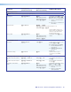
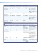
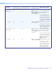
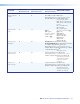
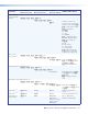
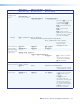
Command and Response Table for IP SIS Commands
Command
ASCII (Telnet)
(Host to Processor)
URL Encoded (Web)
(Host to Processor)
Response
(Processor to Host)
Additional Description
Bidirectional Serial Data Port
Send data string
E
X10!
*
X10(
*
X11)
*
X11!
RS
}
X0@
W
X10(
%2A
X10!
%2A
X11)
%2A
X11!
RS
|
X10@
{Response from command}
]
Example:
E
05 * 4 * 7 * 3L RS
}
<data>
W 05 %2A 4 %2A 7 %2A 3L RS
|
<data>
{Response from command}
NOTES:
•
X10!
= Port number (01-99) (always 2 digits, 01 = rear panel port, 02 = front panel port)
•
X10(
= Time in tens of milliseconds that the MGP Pro will wait until receipt of the first response character before
terminating the command. Default = 10 = 10 ms. Max. = 32767.
•
X11)
= Time in tens of milliseconds that the MGP Pro will wait between characters being received via a serial port
before terminating the current command or receive operation. Default = 20 = 20 ms. Max. = 32767.
•
X11!
= Message length #L or #D. The letter parameter is case sensitive (requires capital D or capital L).
L = Length of the message to be received.
D = Delimiter value. A delimiter of ASCII 0A = 10D.
# = Byte count (for L) or a single ASCII character expressed in decimal form (for D).
The byte count # can be 0-32767. Default = 0.
The ASCII decimal # can be 0-00255. Default = the byte count.
A 3-byte length = 3L. The response includes leading zeros.
•
X10@
= Command data section. For web encoding for
X10@
, be sure to convert non-alphanumeric characters to hex
numbers (see the note on page 49).
• The *
X10(
*
X11)
*
X11!
sequence is optional. If
X10(
and
X11)
are not specified, the default values are used.
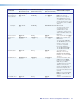
Configure serial
port parameters
24
E
X10!
*
X11^
,
X11&
,
X11*
,
X11(
CP
}
W
X10!
%2A
X11^
%2A
X11&
%2A
X11*
%2A
X11(
CP
|
Cpn
X10!
• Ccp
X11^
,
X11&
,
X11*
,
X11(
CP
]
For port
X10!
, set baud rate
X11^
, parity
X11&
, data bits
X11*
, and stop bits
X11(
.
X11^
= 2400, 4800, 9600,
19200, 38400, or
115200.
X11&
= odd, even, none,
mark, or space.
(Only the first letter is
required.)
X11*
= 7 or 8.
X11(
= 1 or 2.
View serial port
parameters
E
X10!
CP
}
W
X10!
CP
| X11^
,
X11&
,
X11*
,
X11(
CP
]
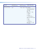
Configure mode
24
E
1 *
X12)
CY
}
W 1 %2A
X12)
CY
|
Cpn1 • Cty
X12)]
Select serial mode
X12)
for
the rear panel RS-232/422
port. For
X12):
0 = RS-232
1 = RS-422.
NOTE: Only the rear panel RS-232/422 port can be configured.
View serial mode
E
X10!
CY
}
W
X10!
CY
| X12)
]
View current port mode.