
User Guide User guide

MGP Pro Series • Operation 14
D
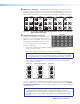
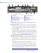
Window Select buttons — Press these buttons to select, activate, or
adjust one of the windows. While a window is selected, all picture
controls are associated with it. The MGP 464 Pro models have four
window selection buttons and the MGP 462 Pro models have two.
E
Window Preset button — Press the Preset Recall/Save and Enter buttons to
save or recall window presets (see Window Presets on page 36).
F
Picture control buttons — Press these buttons to adjust window
and image size, position, brightness, range of dark and light
values (contrast), color, tint, detail, and zoom (magnify or reduce)
(see Picture Controls on page 34).
G
LCD screen — This screen displays messages, menu
information, and your selections (see Menus, Configuration,
and Adjustments on page 16.)
H
Adjust knobs — Turn these horizontal and vertical Adjust knobs
to adjust picture controls and to scroll through preset memory
slots and submenu options (see Menus, Configuration, and
Adjustments).
I
Menu navigation buttons — Press Menu to access the MGP Pro menu
system and step through the menus. From each menu, press Next to
step through its submenus (see Menus, Configuration, and
Adjustments).
J
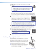
Config port — This configuration port on a 2.5 mm TRS connector is an
alternative to the RS-232/422 port on the MGP Pro rear panel. However,
unlike the rear panel port, it supports only RS-232 (see
C
Remote
RS-232/422 connector on page 8 for a description of the rear panel serial port).
Both of the MGP Pro serial ports are used for system configuration and control.
Commands are received through these ports from the computer, using SIS commands
or the control software. Both serial ports can be active at the same time.
The protocol for this configuration port is 9600 baud, 8 data bits, 1 stop bit, no parity,
and always RS-232.
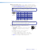
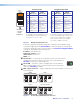
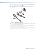
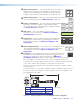
An optional 9-pin D to 2.5 mm TRS configuration cable is available from Extron and can
be used to connect your computer to this port. Figure 12 shows the configuration and
pin assignments of this cable.
6 feet
(1.8 m)
5
1
9
6
Sleeve (Gnd)
Ring
Tip
6
9
9-pin D Connection TRS Plug
Pin 2 Computer Rx line Tip
Pin 3 Computer Tx line Ring
Pin 5 Computer signal ground Sleeve
Figure 12. Optional 9-pin D to 2.5 mm TRS Cable for the Config Port
WINDOW SELECT
3 4
1 2
PRESET
RECALL
/SAVE
WINDOW/
IMAGE
POSITION
WINDOW/
IMAGE
SIZE
BRIGHT
/CONT
COLOR
/TINT
DETAIL
WINDOW/
IMAGE
ZOOM
ADJUST
MENU
NEXT
CONFIG