
User Guide User guide

MGP Pro Series • Installation 9
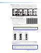
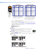
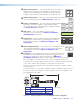
FIG_LAN port wiring
A cable that is wired as T568A at one end
and T568B at the other (Tx and Rx pairs
reversed) is a "crossover" cable.
A cable that is wir
ed the same at both ends
is called a "straight-through" cable because
no pin or pair assignments are swapped.
Both ends of the cable can be T568B
(as shown) or T568A (not shown).
RJ-45
Connector
Insert Twisted
Pair Wires
12345678
Pins:
Crossover Cable Straight-through Cable
Pin
1
2
3
4
5
6
7
8
Wire Color
White-green
Green
White-orange
Blue
White-blue
Orange
White-brown
Brown
Wire Color
T568A
T568B
End 1 End 2 End 1 End 2
White-orange
Orange
White-green
Blue
White-blue
Green
White-brown
Brown
Pin
1
2
3
4
5
6
7
8
Wire Color
Blue
White-blue
White-brown
Brown
Wire Color
T568B
T568B
White-orangeWhite-orange
OrangeOrange
White-greenWhite-green
Blue
White-blue
GreenGreen
White-brown
Brown
Figure 7. Wiring the LAN Connector
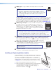
If desired, configure the LAN port by using SIS commands (see the LAN port setup
commands, beginning with the Set IP address command on page 75) or by using the
Comm./IP Configuration menu on the front panel (see Comm./IP Configuration Menu
on page 29). The LAN port default settings are:
IP address: 192.168.254.254
Gateway IP address: 0.0.0.0
Subnet mask: 255.255.0.0
DHCP: off
E
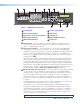
Reset button — Pressing this recessed button causes various IP functions
and Ethernet connection settings to be reset to the factory defaults (see
Resetting on page 40 for more information).
F
Reset LED — This LED, located to the upper-right of the reset button,
blinks a varying number of times to indicate which reset mode has been
entered (see Resetting for details).
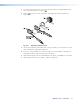
G
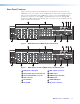
BNC output connectors — Plug an output device into these five BNC connectors, as
shown in figure 8.
R
/R-Y
G
/Y
B
/B-Y
H
/HV
V
RGBHV
R
/R-Y
G
/Y
B
/B-Y
H
/HV
V
RGBS
R
/R-Y
G
/Y
B
/B-Y
H
/HV
V
RGsB
R
/R-Y
G
/Y
B
/B-Y
H
/HV
V
HD Component Video
Figure 8. Connecting to BNC Output Connectors
RESET