
User Guide User guide

MGP Pro Series • Special Applications 99
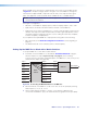
4. Select window 1 on the MGP Pro and configure the input as follows:
a. Set the following input sampling parameters as desired: signal type, horizontal and
vertical start, total pixels, active pixels, and active lines.
b. Set the following picture controls as desired: image size, image position, color, tint,
brightness, and contrast.
c. Set the pixel phase for window 1, then mute the window to display the next window
behind it. For analog inputs only, repeat this step for windows 2, 3, and 4.
d. Save the adjusted settings as Input Preset 1.
5. Save the settings entered in step 4 again as Input Preset 2, 3, and so on, for each input
on the matrix switcher that will be displayed on the output screen via the processor.
NOTE: Each input preset must be saved with the same number as the matrix
switcher input.
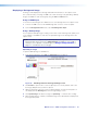
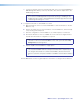
6. Synchronize the MGP Pro to the matrix switcher as follows:
a. Open the MGP Series Control Program.
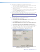
b. From the Tools menu, select Sync MGP Pro Device to Matrix Switcher.... The
Sync MGP Pro to Matrix Switcher window opens.
c. In the IP Address field, enter the matrix switcher IP address.
d. Click Connect To Matrix button. The matrix size of the switcher is displayed to the
right of the button, and its input-output ties are shown in the Matrix Status section.
e. From the drop-down menu in the MGP Input #1 field, select the number of the
matrix switcher output to which you connected the MGP Pro input 1 in step 1.
f. Repeat step e for MGP Pro inputs 2 through 4, making sure to select the number of
the matrix switcher output connector to which you attached the MGP Pro input.
g. Click Take to tie the MGP Pro inputs to the selected switcher outputs.
h. Click Close to close the Sync MGP Pro to Matrix Switcher window.
Figure 41. Example of a Sync MGP Pro to Matrix Switcher Window for an
MGP 464 Pro with Input Ties to a Switcher