User Guide Signal Processors MGP Pro Series Multi-Graphic Processors 68-2469-01 Rev.
Safety Instructions Safety Instructions • English WARNING: This symbol, , when used on the product, is intended to alert the user of the presence of uninsulated dangerous voltage within the product’s enclosure that may present a risk of electric shock. ATTENTION: This symbol, , when used on the product, is intended to alert the user of important operating and maintenance (servicing) instructions in the literature provided with the equipment.
FCC Class A Notice This equipment has been tested and found to comply with the limits for a Class A digital device, pursuant to part 15 of the FCC rules. The Class A limits provide reasonable protection against harmful interference when the equipment is operated in a commercial environment. This equipment generates, uses, and can radiate radio frequency energy and, if not installed and used in accordance with the instruction manual, may cause harmful interference to radio communications.
Conventions Used in this Guide Notifications The following notifications are used in this guide: ATTENTION: Attention indicates a situation that may damage or destroy the product or associated equipment. NOTE: A note draws attention to important information.
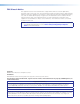
Contents Introduction............................................................ 1 Remote Configuration and Control................. 42 About this Guide.................................................. 1 About the MGP Pro Series Multi-Graphic Processors......................................................... 1 Features.............................................................. 2 Application Diagram............................................ 4 Control Connections...................................
Special Applications........................................... 97 Application 1: Connecting the MGP Pro to a Matrix Switcher................................................. 97 Setting Up the MGP Pro to Work with a Matrix Switcher ............................................ 98 Application 2: Connecting Multiple MGP Pros in Succession (Daisy-chaining)....... 100 Setting up MGPs for Daisy-chaining............ 102 Reference Information..................................... 104 Mounting the MGP Pro ..........
Introduction This section provides an overview of the MGP Pro Multi-Graphic Processors, including information about the following: • About this Guide • About the MGP Pro Series Multi-Graphic Processors • Features • Application Diagram About this Guide This guide discusses how to install, configure, and operate the Extron MGP Pro Series and the multi-graphic processors. Throughout this guide, the terms “MGP,” “MGP Pro,” and “processor” are used interchangeably to refer to all models of the products.
Features • Inputs — Four fully configurable video inputs on BNC connectors accept RGBHV (up to 1920x1200 and 2K), HDTV component video (up to 1080p @ 60 Hz), S-video, and composite video signals. In addition, the MGP 464 Pro and 462 Pro DI models have four HDMI inputs, and the MGP 464 Pro and 462 Pro 3G-SDI models have two 3G/HD-SDI and two HDMI inputs. • Virtual inputs — 15 virtual inputs can be configured through software to accept standard definition component video, S-video, and composite video.
• Auto Image — Auto Image automatically sizes, centers, and optimizes the image to the scaled output rate, filling the window. • EDID emulation — The MGP provides selectable resolutions and refresh rates, enabling you to specify the rate of the incoming signal and ensure proper communication with the video source.
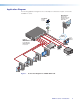
Application Diagram The following application diagram shows an example of how devices may be connected to the MGP Pro series.
Installation This section describes the installation procedures for the MGP Pro Series Multi-Graphic Processor and the connectors on the rear panel. Topics include: • Installation Overview • Rear Panel Features • Installing or Replacing Button Labels Installation Overview The MGP Processor can be connected to as many as 19 input devices simultaneously, and up to two output devices. Follow these steps to install the MGP Pro: 1.
Rear Panel Features Figure 2 shows the rear panel of the MGP 464 Pro DI and 462 Pro DI, which have four HDMI input connectors. Figure 3 shows the MGP 464 Pro and 462 Pro 3G-SDI rear panel, which has two 3G/HD-SDI and two HDMI input connectors. The standard MGP 464 Pro and 462 Pro models do not have HDMI or 3G/HD-SDI input connectors (although all models have HDMI output and Live Background connectors). In all other respects the rear panels are identical for all models. Figure 2.
A BNC inputs 1 through 4 — Plug RGB, high or standard definition component video, S-video, or composite video sources into these fully configurable BNC connectors, as shown in figure 4. Configure these connectors for the desired signal types via the front panel, the Windows-based control software, SIS commands, or the MGP web pages. 1 RGBHV Video R/R-Y R/R-Y G/Y VID H/HV G/Y VID B/C B-Y V B/C B-Y Figure 4.
C Remote RS-232/422 connector — Plug a computer or other RS-232 or RS-422 host device into this female 9-pin D connector. Wire the connector as shown in figure 6 (see the Remote Configuration and Control section beginning on page 42 for more information on controlling the MGP Pro remotely via RS-232 or RS-422). NOTE: The MGP Pro also has an RS-232-only Config port on a 2.5 mm tip-ringsleeve (TRS) connector on the front panel. For information on this port, see J Config port on page 14.
FIG_LAN port wiring Crossover Cable Pins: 12345678 End 1 Wire Color Pin Insert Twisted Pair Wires RJ-45 Connector Straight-through Cable End 2 Wire Color Pin End 1 Wire Color End 2 Wire Color 1 White-green White-orange 1 White-orange White-orange 2 Green Orange 2 Orange Orange 3 White-orange White-green 3 White-green White-green 4 Blue Blue 4 Blue Blue 5 White-blue White-blue 5 White-blue White-blue 6 Orange Green 6 Green Green 7 White-brown White-brown 7 W
H HDMI output — Plug an HDMI or DVI output device into this HDMI connector. NOTES: • When two output devices are attached to the BNC connectors and to the HDMI connector, both outputs display the same image. HDMI • Connecting a DVI display to this HDMI connector requires an adapter cable. LockIt brackets: LockIt cable lacing brackets, one for each HDMI input and the output connector, are provided with the MGP Pro.
3. Locate the small corner notch on the lens cap, and slide the screwdriver between the lens cap and the diffuser (see figure 9, 3). 4. Using a rotating motion of the screwdriver, carefully pry the two pieces apart (see figure 9, 4). Figure 9. Replacing a Button Label 5. Lift out the transparent square label that you want to replace. You may need to use the small screwdriver to gently pry the label out. 6.
Operation This section describes the setup and operating procedures for the MGP Pro and includes the following sections: • Front Panel Features • Power-up and Default Cycle • Window Select Buttons • Input Selection • Menus, Configuration, and Adjustments • Picture Controls • Auto Memories • Memory Presets • Additional Functions You can set up and operate the MGP Pro using: • The front panel controls • A computer, a touch screen panel, or any other device that can send and receive serial
Figure 11. MGP 462 Pro Front Panel A Freeze button B Input selection buttons C Virtual video input selection buttons D Window Select buttons E Window Preset buttons F Picture control buttons G LCD screen H Adjust knobs I Menu navigation buttons J Config port A Freeze button — Press this button to freeze the image in the currently selected window on the display. The image remains frozen until the Freeze button is pressed again, or a different input is selected.
D Window Select buttons — Press these buttons to select, activate, or adjust one of the windows. While a window is selected, all picture controls are associated with it. The MGP 464 Pro models have four window selection buttons and the MGP 462 Pro models have two. WINDOW SELECT E Window Preset button — Press the Preset Recall/Save and Enter buttons to save or recall window presets (see Window Presets on page 36).
Power-up and Default Cycle When you first plug the MGP Pro into a power source, the LCD screen displays an initial screen, which contains the product name, model, and firmware version. This is followed by the default cycle of screens showing the current input type for each window and the output resolution and refresh rate. These messages continue to cycle on the LCD screen when the menu system is not in use. The following flow diagram shows the order in which these screens appear. Figure 13.
Input Selection The MGP Pro front panel contains a set of four input buttons that enable you to select RGB, HD component video, S-video, or composite video inputs for windows 1 through 4. On DI and 3G-SDI models, these buttons can select the HDMI or SDI input. The front panel also contains 15 virtual input buttons that enable you to select only component video, S-video, or composite video inputs. Selecting an Input Before you can select an input, you must first select a window, as follows: 1.
3. Submenu options — When the Main menu item that you want to configure is displayed on the LCD screen, press the Next button (at the right of the Menu button) to cycle through the submenu options of the displayed menu. 4. Adjustments — With a desired submenu option displayed, rotate the horizontal ([) and vertical ({) Adjust knobs clockwise or counterclockwise to display and select the parameters available for the option. 5.
Main menu flow Figure 14.
Auto Image Menu The Auto Image menu causes the MGP Pro to perform an automatic image adjustment in the selected window. Auto Image measures where the active area starts and stops, and adjusts input sampling accordingly, so that the image fills the window. When an input is connected, the processor measures the sync frequencies of the incoming video source and sets the active image area, total image area, and sampling frequency according to a table stored on the MGP Pro.
Input Configuration Menu The Input Configuration menu allows you to select a video signal type for each of the four fully configurable inputs. All of these inputs can accept the following video signals: RGB, YUV-HD, YUVi, RGBcvS, S-video, composite video, HDMI (MGP Pro DI and 3G-SDI models only), and 3G/HD-SDI (MGP Pro 3G-SDI models only). RGB is the default.
Input configuration submenu adjustments The table below shows how to make the selections and adjustments that are accessed through the Input Configuration submenus. Input Configuration Submenu Horizontal Knob Adjustment Vertical Knob Adjustment Video type Select input 1, 2, 3, or 4. Select the desired video format for the displayed input. Default is RGB Film mode Select input 1, 2, 3, or 4. For low resolution inputs.
Output Configuration Menu The Output Configuration menu allows you to set output resolution, refresh rate, output signal type, and sync polarity. The following flow diagram shows the Output Configuration submenus and the adjustments that can be made from them. Figure 17.
Resolution Refresh Rates in Hz 50 Hz 60 Hz 72 Hz 96 Hz 100 Hz 120 Hz 640 x 480 X X X X X X 800 x 600 X X X X X X 852 x 480 X X X X X 1024 x 768 X X X X 1024 x 852 X X X X 1024 x 1024 X X X 1280 x 768 X X X 1280 x 1024 X X X 1360 x 765 X X X 1365 x 768 X X X 1366 x 768 X X X 1365 x 1024 X X 1400 x 1050 X X 1600 x 1200 X X 480p 24 Hz 59.94 Hz 29.
Analog Format submenu Rotate either the horizontal Adjust ([) or the vertical Adjust ({) knob to select the analog output signal type required by the display device. Available signal types are RGBHV, RGsB, RGBS, YUV bi-level and YUV tri-level. The default is RGBHV. Sync Polarity submenu The display device may require a particular combination of horizontal (H) and vertical (V) sync signal polarities. Rotate either the horizontal Adjust ([) or the vertical Adjust ({) knob to select the sync polarity.
Window Priority submenu The Window Priority submenu allows you to set how the windows will overlap one another or “stack” on the display. For example, by default the window with priority 1 is displayed in front of all the other windows. If the top priority window is sized to fill the screen, the other windows are not visible. By default, the Window Priority submenu displays the numbers of the windows in order, from left to right, with window 1 having first priority. To change the priority of a window: 1.
• Center wipe — A center wipe causes the new window to appear to unroll over the other one in one of two ways: • In from the top and bottom edges to the center of the window • Out from the center to the top and bottom edges of the window A center wipe can have a soft (fuzzy) or a hard (sharp) leading edge.
Background Capture Menu The Background Capture menu allows you to capture the image currently on the output screen and save it as a bitmap (.bmp) file with one of 16 designated image names. You can then recall the image and use it as a background. Background Capture also can be done via the Windows-based control software (see the MGP Series Control Program help file). Figure 19.
3. Rotate either Adjust knob to select a background file name (bkg01.bmp through bkg16.bmp) with which to save the image. NOTE: You can save the background image only under one of the file names on this menu (you cannot create a different name for it).
Comm./IP Configuration Menu Use the Comm./IP Configuration menu to view and edit the serial communication port configuration and the MGP Pro IP addresses. The Comm./IP Configuration menu consists of two levels: view and edit. Figure 20. Communication/IP Configuration Menu Flow Viewing serial port and IP settings When you first reach the Comm./IP Configuration menu, the view level is displayed. At this level, all the screens that you cycle through by pressing Next show the current settings.
4. When finished editing the settings for the selected item, either press Next to display the editing screen for the next item, or press Menu to exit serial and IP edit mode and display the next menu (Advanced Configuration). The following screens are provided for editing parameters: • Serial Config: Configure the serial port by switching between RS-232 and RS-422, and selecting the baud rate. • Set DHCP Mode: Set DHCP to On or Off. NOTE: DHCP must be off before you can edit the IP addresses.
Background Color submenu Rotate either Adjust knob to select a background color for the output screen. Options are NONE, RED, GREEN, BLUE, WHITE, MAGENTA, CYAN, YELLOW, STORED-IMAGE, LIVE BKG, and USER DEFINED. • NONE, the default setting, produces a black background. • STORED-IMAGE is the saved background that was most recently recalled. Select this option if you want to return to the recalled background after having changed to a different background color.
FIG_Test patterns Colorbars (8) X-Hatch (16 x 12) 4x4 X-Hatch Grayscale Ramp Alt. Pixels White Field Crop 4x3 4x3 16x9 4x3 16x9 4 x3 4 x3 4 x3 Side-By-Side (4 x 3 crop) Side-By-Side (16 x 9 crop) Quad Split PIP Images (4 x 3) 1.85 Aspect 2.35 Aspect 4 x3 16x9 4 x3 4 x3 PIP Images (16 x 9) 1.78 Aspect Figure 22.
Input EDID submenu This submenu lets you define resolutions and refresh rates (EDID) for all the digital inputs and the live background input. The default is CUSTOM. NOTE: The selected EDID is assigned to all the configurable inputs, including the live background.
Factory Default submenu This submenu lets you reset the MGP Pro to the default settings with which it was delivered from the factory. Press the Detail button to initiate the reset. Adding and Configuring Window Text You can add a text box or label containing up to 16 characters to each window. You can also specify several parameters for the text label, including text size and color, label background color, label border color, and the position of the text box on the screen.
Picture Controls Summary The following table explains the functions of the Picture Control buttons and how to make adjustments. In this table, image number nn is the input number. Button Display Function Range Adjust Knob Window/ Image Size WINDOW_n SIZE: H=nnnn V=nnnn Enlarge or shrink window n. Min: 1/16 of the output rate Max: Output rate For H (width): Horizontal [ Adjust knob Enlarge or shrink the image of input nn within the window.
Auto Memories Whenever changes are made to the settings described in the previous pages, the MGP Pro automatically saves the changes in memory. These settings are saved based on the input frequency and are later recalled when the identical resolution is applied to the configured input. These memory locations are separate from the input presets.
Saving To #001 - - - - - INPUT 1 - - - - WINDOW PRESET #001 SAVED 3. Rotate either Adjust knob to select one of the 128 available window preset locations in which to save the settings. WINDOW PRESET 4. PressWINDOW the Enter button to save the current window setting in the preset location that you Save ToPRESET #001 selected. The LCD screen shows a message indicating that the preset is being saved to Recall #001 woINP the selected memory location, followed by a message that the preset has been saved.
Default presets Figures 23 and 24 show the factory default preset window configurations for the fourwindow and two-window models. These presets can be used for any output rate. If you overwrite them, you can recover them by selecting Factory Defaults from the Advanced Configuration menu (see Advanced Configuration Menu on page 30).
Input Presets The MGP Pro has 128 input preset slots, which can save signal type, input configuration settings, picture control settings, and window text for any of the inputs. These presets can be saved and recalled using the Windows-based control software (see the software help file) or by SIS commands (see the Remote Configuration and Control section beginning on page 42).
By disabling HDCP authorization on one of the MGP Pro HDMI inputs, you ensure that the PC with non-HDCP protected content will determine that the signal path does not support HDCP, and therefore will not encrypt its output. With HDCP authorization disabled on the MGP input, you are able to view your non-HDCP protected content from the video output of the MGP Pro.
Reset Modes Summary Mode Use Factory Firmware 1 Run or Stop Events 3 Reset All IP Settings 4 Result Purpose Hold in the Reset button while applying Restores the factory-installed firmware. It power to the MGP Pro. does not clear the current configuration. Mode 1 can be used to remove a version of firmware if incompatibility issues arise. Hold in the Reset button until Turns events on or off.
Remote Configuration and Control This section describes the serial and Ethernet connections through which the Extron Simple Instruction Set commands can be issued to the MGP Pro. It also lists the commands that are available for controlling and configuring the MGP Processors.
Ethernet Port The rear panel Ethernet connector on the MGP Pro can be connected to an Ethernet LAN or WAN. Communication between the MGP Pro and the controlling device can be via Extron DataViewer or Telnet (a TCP socket using port 23). The Telnet port can be changed, if necessary, via SIS (for information on connecting via Telnet, see Connecting as a Telnet Client on page 108). The Ethernet connection makes SIS control of the MGP Pro possible using a computer connected to the same LAN or WAN.
• Reconfig Reconfig Reconfig Reconfig The MGP Pro sends a Reconfig message as each of the four windows is configured via the new connection. • Out n In nn (where Out n is the window number, and In nn is the input number). The MGP Pro sends this response when an input is switched. Error Responses When the MGP Pro receives a valid SIS command, it executes the command and sends a response to the host device.
The command and response tables list valid ASCII (for Telnet) command codes, the corresponding URL encoded (for web browsers) command codes, the responses of the processor to the host, and a description of the command function or results from executing the command. Entering SIS Commands • Upper- and lowercase letters may be used interchangeably in the command field unless otherwise specified. • Commands may be sent back-to-back without spaces, for example, 2*2!2*0B.
MGP Pro commands X! = Input number (1-20). 20 = live background (for HDCP status only) X& = X@ = Window number 0 = All windows (available only for freeze and window mute) 1 = Window 1 2 = Window 2 3 = Window 3 (MGP 464 Pro models only) 4 = Window 4 (MGP 464 Pro models only) Window text, 16 characters maximum.
X1@ = X1# = X1$ = X1% = X1^ = Window transition effect type 1 = Cut 2 = Dissolve 3 = Soft wipe up 4 = Soft wipe down 5 = Soft wipe right 6 = Soft wipe left 7 = Soft wipe center in 8 = Soft wipe center out 9 = Soft wipe square in 10 = Soft wipe square out 11 = Soft wipe curtain in 12 = Soft wipe curtain out 13 = Hard wipe up 14 = Hard wipe down 15 = Hard wipe right 16 = Hard wipe left 17 = Hard wipe center in 18 = Hard wipe center out 19 = Hard wipe square in 20 = Hard wipe square out 21 = Hard wipe curtai
X3^ = Output polarity 0 = H-/V- (default) 1 = H-/V+ 2 = H+/V3 = H+/V+ X3& = Output sync format 1 = RGBHV 2 = RGBS 3 = RGsB 4 = YUV bi-level 5 = YUV tri-level X3* = Label text size 1 = small 2 = medium 3 = large X3( = Label border color 0 = off (no border) 1 = red 2 = green 3 = blue 4 = white 5 = magenta 6 = cyan 7 = yellow 8 = black 9 = translucent X4) = Label text color 1 = red 2 = green 3 = blue 4 = white 5 = magenta 6 = cyan 7 = yellow 8 = black X4! = Label text background color 0 = off (no ba
IP-specific commands X10! = Specific port number (01-99) The port number is represented as two ASCII characters (2 bytes). For example, port 05 would be represented as 30 35 in hexadecimal. X11$ = Verbose response mode 0 = Clear/none (default for Telnet connections). 1 = Verbose mode is on (enabled) (default for RS-232 or RS-422 connections). 2 = Verbose mode is off, tagged responses are sent for queries (tagged responses are enabled).
X11& = Parity (only the first letter is needed): O[dd] E[ven] N[one] M[ark] S[pace] X13! = X13@ = X13# = X13$ = Number of bytes to read X11* = X11( = X12) = Data bits: 7 or 8 X13% = Default name: a combination of the model-name and the last three character pairs of the unit MAC address (for example, MGP Pro-464-00-02-3D) X13^ = Extended security (password) levels: 1-10 The response is 2 digits with a leading zero.
Command and Response Table for MGP Pro SIS Commands ASCII (Telnet) (Host to Processor) Response (Processor to Host) Select an input X! * X@! Out X@ •In X! ] View input X@! X! ] Set video type X! * X# \ X! Typ X# ] View video type X! \ X# ] Command Additional Description Input Selection Select input source X! for window X@. View the input channel for the selected window. X! = 1-19. X@ = 0-4. 0 = all windows. Input Video Type Set input X! to format X#.
ASCII (Telnet) (Host to Processor) Response (Processor to Host) Mute window X@ * 1B X@ Blk1 ] Unmute window X@ * 0B X@ Blk0 ] View blanking status X@ B X$ ] Set priority X@ * X@ * X@ * X@ ~ Pri X@ X@ X@ X@ ] View priority ~ X@ X@ X@ X@ ] Select effect 4 * X1@ # Eff X1@ ] View effect 4 # X1@ ] Select duration 5 * X1( # Dur X1( ] View duration 5# X1( ] Command Additional Description Window Blanking (Muting) Blank (mute) window X@ using the currently selected transition effect.
Command ASCII (Telnet) (Host to Processor) Response (Processor to Host) Additional Description Window Preset Effect NOTE: You can select additional window preset transition effects using the MGP Series Control Program (see the control software help file for more information).
ASCII (Telnet) (Host to Processor) Response (Processor to Host) Set a specific value X@ * X1! D X@ Det X1! ] Increment detail level X@ + D X@ Det X1! ] Decrement detail level X@ – D X@ Det X1! ] View detail value X@ D X1! ] Command Additional Description Detail Filter Set the detail (sharpness) level for window X@ to X1!. X@ = 0-4. 0 = all windows. X1! = 0-127. Select the next higher sharpness level. Select the next lower sharpness level. View the current sharpness level setting.
ASCII (Telnet) (Host to Processor) Response (Processor to Host) Set a specific value 2 * X@ * X2! / X@ Ivp X2! ] Increment vertical image shift Decrement vertical image shift 2 * X@ + / 2 * X@ – / X@ Ivp X2! ] X@ Ivp X2! ] View vertical image shift amount 2 * X@ / X2! ] View the current setting for vertical centering of the image in window X@.
ASCII (Telnet) (Host to Processor) Response (Processor to Host) Set a specific value 2 * X@ * X2# ; X@ Ivs X2# ] Increase vertical size of image 2 * X@ + ; X@ Ivs X2# ] Decrease vertical size of image View vertical size of image 2 * X@ – ; X@ Ivs X2# ] 2 * X@ ; X2# ] 2 X! * X@ # Pcc X! ] Command Additional Description Vertical Size (Image) Set the height of the image in window X@ to X2#. X@ = 0-4. 0 = all windows. For X2#: Minimum = 1/16 the size of the active input area.
ASCII (Telnet) (Host to Processor) Response (Processor to Host) Zoom in 1 * X@ + { X@ Wzm ] Zoom out 1 * X@ – { X@ Wzm ] Zoom in 2 * X@ + { X@ Izm ] Zoom out 2 * X@ – { X@ Izm ] Recall window preset without input 1 * X1$ . Rpr 1 * X1$ ] Recall window preset with input. Preset preview 2 * X1$ . Save preset 2 * X1$, View last recalled preset 1. Command Additional Description Window Zoom Increase the size of window X@ while keeping its aspect ratio constant.
Command ASCII (Telnet) (Host to Processor) Response (Processor to Host) Additional Description Window Preset Naming NOTE: Window preset names cannot be viewed on the LCD screen. They can be viewed via the MGP Series Control Program or SIS commands. Write preset name E X1$ , X& NP } Nmp X1$ , X& ] Give the window preset X1$ the name X&. X1$ = 1-128. View the name for window preset X1$.
ASCII (Telnet) (Host to Processor) Response (Processor to Host) Set a specific value 11 * X! * X1* # Tpx X! * X1* ] Increment total pixels value 11 * X! + # Tpx X! * X1* ] Decrement total pixels value 11 * X! – # Tpx X! * X1* ] View total pixels setting 11 * X! # X1* ] Set a specific value 12 * X! * X1* # Apx X! * X1* ] Increment active pixels value 12 * X! + # Apx X! * X1* ] Decrement active pixels value 12 * X! – # Apx X! * X1* ] View active pixels setting 12 * X! # Command Addit
Command ASCII (Telnet) (Host to Processor) Response (Processor to Host) Additional Description Output Scaler Resolution and Rate Set output resolution and scan rate X( * X1^ = Rte X( * X1^ ] For X(: 1 = 640x480 2 = 800x600 3 = 852x480 4 = 1024x768 5 = 1024x852 6 = 1024x1024 7 = 1280x768 8 = 1280x1024 9 = 1360x765 10 = 1365x768 11 = 1366x768 12 = 1365x1024 13 = 1400x1050 14 = 1600x1200 View output rate settings = View output rate details 0= Select scaler output resolution X( and scan rate X1^.
Command ASCII (Telnet) (Host to Processor) Response (Processor to Host) X% J Tst X% ] Additional Description Test Pattern Set test pattern Select test pattern X%. For X%: 0 = Off (none) 1 = Colorbars 2 = X-Hatch (16 x 12) 3 = 4 x 4 X-Hatch 4 = Grayscale 5 = Ramp 6 = Alt. Pixels 7 = White Field 8 = Crop 9 = Side-By-Side (4 x 3 crop) 10 = Quad Split (4 x 4) 11 = PIP Images (4 x 3 or 6 x 9 PIP columns) 12 = 1.78 Aspect (4 x 3/16 x 9) 13 = 1.85 Aspect (4 x 3/16 x 9) 14 = 2.35 Aspect (4 x 3/16 x 9).
Command ASCII (Telnet) (Host to Processor) Response (Processor to Host) Additional Description Special Functions (continued) Set output sync format 2 * X3& # Syn X3& ] View output sync format 2# X3& ] Set blue mode to On or Off 3 * X$ # Blu X$ ] View blue mode status 3# X$ ] Set text position 6 * X@ * X^ # X@ Tlc X^ ] View text position 6 * X@ # X^ ] Set text size 10 * X3* # Tsz X3* ] View text size 10 # X3* ] Set text border color 14 * X@ * X3( # X@ Txb X3( ] View text border
Command ASCII (Telnet) (Host to Processor) Response (Processor to Host) Additional Description Special Functions (continued) Set text color 16 * X@ * X4) # X@ Txc X4) ] View text color 16 * X@ # X4) ] Set text background color 17 * X@ * X4! # X@ Tbc X4! ] View text background color 17 * X@ # X4! ] Set window border color 9 * X@ * X4@ # X@ Brd X4@ ] View window border color 9 * X@ # X4@ ] Set the color of the text in the label in window X@ to X4).
Command ASCII (Telnet) (Host to Processor) Response (Processor to Host) Additional Description Special Functions (continued) Set screen background color 8 * X4# # Bkg X4# ] View background color 8# X4# ] Set a custom color 22 * X2% * X2% * X2% # Ubk X2% * X2% * X2% ] View custom color 22# Ubk X2% * X2% * X2% ] E 0 , filename MF } Ims filename ] Set background color X4# for the output screen.
Command ASCII (Telnet) (Host to Processor) Response (Processor to Host) Additional Description HDCP/Signal Status NOTE: These commands are applied only to digital inputs. Query input E I X! HDCP } X2( ] With tagged response (verbose mode 2 or 3): Hdcp I X! * X2( ] Query all inputs Query output E I HDCP } E O X! HDCP } View HDCP status X2( for input X! (HDMI inputs only). For X2(: 0 = No source or sink detected. 1 = Source or sink with HDCP detected. 2 = No source or sink detected with HDCP.
Command ASCII (Telnet) (Host to Processor) Response (Processor to Host) X@ * I Chn X! • Typ X# • Std X1) • Blk X% ] View input number, video signal type, input signal standard, and blanking (muting) status in window X@. X! = 1-19. X# = signal type. For X#: 1 = RGB 2 = YUV-HD 3 = RGBcvS 4 = YUVi 5 = S-video 6 = Composite video 7 = HDMI or 3G/HD-SDI. X1) = signal standard. For X1): 0 = None 1 = NTSC 2 = PAL 4 = SECAM – = Not applicable. X$ = muting status. For X$: 1 = muted 0 = unmuted.
Command and Response Table for IP SIS Commands Command ASCII (Telnet) (Host to Processor) URL Encoded (Web) (Host to Processor) Response (Processor to Host) Additional Description Bidirectional Serial Data Port Send data string E X10! * X10( * X11) * X11! RS } X0@ W X10( %2A X10! %2A X11) %2A X11! RS | X10@ {Response from command} ] Example: E 05 * 4 * 7 * 3L RS } W 05 %2A 4 %2A 7 %2A 3L RS | {Response from command} NOTES: • X10! = • X10( = Port number (01-99) (always 2 digits, 01
Command ASCII (Telnet) (Host to Processor) URL Encoded (Web) (Host to Processor) Response (Processor to Host) Additional Description Bi-directional Serial Data Port (continued) Configure flow control24 E X10! * X12! , X12@ CF } W X10! %02A X12! %02C X12@ CF | Cpn X10! • Cfl X12! , X12@ ] For port X10!, set flow control type X12! with X12@ ms between bytes. For X12!: H = Hardware. S = Software. N = None (default). X12@ = 0000 through 0001. Default = 0 ms.
ASCII (Telnet) URL Encoded (Web) (Host to Processor) (Processor to Host) Set current connection port timeout period E 0 * X13* TC } W 0 %2A X13* TC | Pti 0 * X13* ] View current connection port timeout period E 0TC } W 0TC| X13* ] Set global IP port timeout period E 1 * X13* TC } W 1 %2A X13* TC | Pti 1 * X13* ] View global port timeout period E 1TC } W 1TC | X13* ] Command (Host to Processor) Response Additional Description Ethernet Port Set number of seconds (in tens of seconds) bef
Command ASCII (Telnet) (Host to Processor) URL Encoded (Web) Response Additional Description (Host to Processor) (Processor to Host) 3Q X10$ (plus web ver.-desc-UL date/time) ] Firmware Version Requests (continued) Query factory firmware version Example: Query updated firmware version Example: 3Q 3Q 3Q 4Q 4Q 4Q 4Q With tagged response – verbose modes 2 and 3: Ver03 * X10$ (plus web ver.-desc-UL date/time)] Factory-installed firmware is not user-replaceable.
Command ASCII (Telnet) (Host to Processor) URL Encoded (Web) Response Additional Description (Host to Processor) (Processor to Host) 60-1258-nn or 60-1259-nn ] With tagged response – verbose modes 2 and 3: Pno 60-1258-nn or Pno 60-1259-nn ] Show unit part number. MGP 462 Pro is 60-1258-nn. MGP 464 Pro is 60-1259-nn. For nn: 01 = standard model 02 = DI model 03 = 3G-SDI model. X4$ ] Show unit model name X4$.
Command ASCII (Telnet) (Host to Processor) URL Encoded (Web) (Host to Processor) Response (Processor to Host) Additional Description Event Control Read event buffer memory27 Write event to memory buffer24, 27 E X12% , X12^ , X12& , X12* E } W X12% , X12^ , X12& , X12* E| X13( ] E X12% , X12^ , X12& , X12( , X12* E } W X12% , X12^ , X12& , X12( , X12* E| Ewr X12% , X12( ] Read string from event buffer memory27 E X12% , X12^ , X12& , X13! FE } W X12% , X12^ , X12& , X13! FE| {string} ] Read the co
Command ASCII (Telnet) (Host to Processor) URL Encoded (Web) Response Additional Description (Host to Processor) (Processor to Host) W X13@,X13#,X13$ CR| Ipr X13@,X13#,X13$ ] E-mail Commands Configure e-mail events24 X13@,X13#,X13$ CR } When event X13@ occurs, end e-mail notification X13$ to recipient address X13#. X13@ = e-mail event number (1-64). X13# = e-mail recipient address. X13$ = name of e-mail notification file to be sent (first file line is the subject and the rest is the e-mail body).
Command ASCII (Telnet) (Host to Processor) URL Encoded (Web) Response (Host to Processor) (Processor to Host) E • CN } W %20 CN | Ipn • X13% ] E • CN } W %20 CN | Read unit name Set time and date24 E CN } E X10^ CT } W CN | W X10^ CT | Read time/date E CT } W CT | Set GMT offset24 E X10# CZ } W X10# CZ | Read GMT offset E CZ } W CZ | Additional Description IP Setup Commands (continued) Set unit name to factory default24 Example: X13% is the name the processor was shipped with: MGP
Command ASCII (Telnet) (Host to Processor) URL Encoded (Web) Response (Host to Processor) (Processor to Host) Additional Description IP Setup Commands (continued) Set daylight saving time24 E X12$ CX } W X12$ CX | Ipx X12$ ] Read daylight saving time Set DHCP on24 E CX } W CX | X12$ ] E 1DH } W 1DH | Idh1 ] Set DHCP off24 View DHCP mode E 0DH } E DH } W 0DH | W DH | Idh0 ] Idh X$ ] Set IP address24 E X10& CI } W X10& CI | Ipi • X10& ] Read IP address24 E CI } W CI | X10& ] Rea
Command ASCII (Telnet) (Host to Processor) URL Encoded (Web) Response (Host to Processor) (Processor to Host) Additional Description IP Setup Commands (continued) Set gateway address24 E X10& CG } W X10& CG | Ipg • X10& ] Read gateway address Set administrator password E CG } W CG | X10& ] E X12# CA } W X12# CA | Ipa • X13) ] Clear administrator password24 E • CA } W %20 CA | Ipa • ] Set IP address X10& (nnn.nnn.nnn.nnn) for your gateway. Leading zeros are optional.
Command ASCII (Telnet) (Host to Processor) URL Encoded (Web) Response (Host to Processor) (Processor to Host) W X11$ CV | X11$ ] Additional Description IP Setup Commands (continued) Set verbose mode24 E X11$ CV } Enable or disable verbose mode type X11$. For X11$: 0 = verbose mode and tagged responses disabled (default for Telnet connections) 1 = verbose mode enabled (default for RS-232 or RS-422 connections).
Command ASCII (Telnet) (Host to Processor) URL Encoded (Web) Response Additional Description (Host to Processor) (Processor to Host) E {port#} MH } W {port#} MH| Pmh {port#} ] E 80MH } W 80MH| Pmh 00080 ] E 0MH } W 0MH| Pmh 00000 ] E MH } W MH| {port#} ] E {port#} MD } W {port#} MD| Pmd {port#} ] E 2001MD } W 2001MD| Pmd 02001 ] E 0MD } W 0MD| Pmd 00000 ] E MD } W MD| {port#} ] E CC } W CC| {Number of connections} ] E DF } W DF| (See below.) E LF } W LF| (See below.
Command ASCII (Telnet) (Host to Processor) URL Encoded (Web) (Host to Processor) Response (Processor to Host) Additional Description Stream Files via Telnet, RS-232, or RS-422 Load file to user flash memory E +UF filesize, filename } {Raw unprocessed data in file up to filesize} Retrieve file from user flash memory E filename SF } Upl ] Responds with 4 bytes of file size + raw unprocessed data in file.
Command ASCII (Telnet) (Host to Processor) URL Encoded (Web) (Host to Processor) Response (Processor to Host) Additional Description Reset (Zap) / Erase Commands (continued) Reset all device settings to factory default24 Absolute system reset24 Absolute reset retaining IP24 E ZXXX } W ZXXX | Zpx ] IP-related settings and flash memory are not reset.
Windows-based Control Software The MGP Series Control Program provides a convenient way to configure the inputs, output, windows, and images in each window. It also lets you save and recall input and window presets, and perform nearly all the other functions that can be accomplished via the front panel controls, the SIS commands, or the embedded web pages.
6. Click the Download MGPSeriesSetupVnxn.exe button. Depending on your browser and Windows version, one of the following appears: • A File Download - Security Warning window opens. On this window, click Run. When a second File Download - Security Warning window opens, click Run on it to start the firmware installation wizard. • A button containing the name of the firmware file appears at the bottom of the browser screen. Click this button to display an Open File - Security Warning window.
FIG_Comm Type Selection Figure 27. Comm Port Selection Window with TCP/IP and RS232 Tabs • Select the TCP/IP tab if you are using the LAN port. If you will be uploading firmware, you should use this connection. • Select the RS232 tab if you are using a serial ports. (The front panel port supports only RS-232. The rear panel 9-pin serial port supports RS-232 and RS-422.) 3. On the selected tab, enter the information for your communication type and click OK.
HTML Configuration and Control This section provides procedures for accessing and using the MGP Pro embedded web pages. Topics include: • Accessing the Web Pages • Viewing System Status • Using the Configuration Pages • Using the File Management Page • Using the Background Page The MGP Pro series can be controlled and configured using HTML web pages that are accessed over a network or from a local PC connected to the MGP Pro LAN port.
4. Press the key. If the MGP Pro HTML pages are not password protected, the browser displays a start page as described in step 5. If the MGP Pro HTML pages are password protected, the browser displays the Internet Explorer Connect To dialog box (below left) or the Authentication Required dialog box (below right) (Google® Chrome® or Mozilla® Firefox®.) Figure 29. Example of a Connect To Dialog Box a. Enter the administrator or user password in the Password field.
Viewing System Status The System Status web page, accessed by clicking the Status tab, provides information on the current settings of your MGP Pro. Changes must be made via the Configuration web pages, the MGP Series Control Program, SIS commands, or the MGP Pro front panel. Personnel who have user access can view this page but cannot access the Configuration pages. They see only the Status and Background tabs. Figure 30 shows a typical MGP Pro System Status web page. Figure 30.
Using the Configuration Pages There are three Configuration pages, which only administrators can access. When you click the Configuration tab, these pages are listed on the sidebar menu at the left of the screen. The following sections describe the changes you can make from these pages. System Settings Page On the System Settings page (figure 31), you can set IP parameters for the MGP Pro. 1 Figure 31. System Settings Page To change your system settings: 1.
DHCP radio buttons The DHCP On radio button directs the MGP Pro to ignore any entered IP addresses and to obtain its IP address from a Dynamic Host Configuration Protocol (DHCP) server (if the network is DHCP capable). The DHCP Off radio button turns DHCP off. Contact the local system administrator for the setting of this control. IP Address field The IP Address field contains the IP address of the connected MGP Pro. This value is encoded in the MGP Pro flash memory.
Date/Time settings fields The Date/Time Settings section provides a location for viewing and setting the time functions. Figure 32. Date/Time Settings Section To change the date and time settings: 1. Click the drop box for the desired variable. The adjustable variables are month, day, year, hours, minutes, am or pm, and (time) zone. A drop-down scroll box appears (the Month drop box is selected in figure 32). 2. Click and drag the slider or click the Scroll Up until the desired variable is visible.
Passwords Page The Passwords page lets you assign an administrator or user password to control access to the MGP Pro web pages. To access this page, click the Configuration tab, then the Passwords link on the left sidebar menu (see figure 33, 1). NOTE: • An administrator password must be in place before a user password can be assigned. • Passwords must contain 4 to 12 alphanumeric characters. Symbols and spaces are not allowed, and the passwords are case sensitive. 1 Figure 33.
Firmware Upgrade Page The Firmware Upgrade page enables you to install a new version of firmware to your MGP Pro. (The same firmware is used for both the MGP 464 Pro and the MGP 462 Pro.) You can download the latest firmware version from the Extron website to your computer (see Updating the Firmware beginning on page 111 for more details on firmware updating). To access the Firmware Upgrade page, click the Configuration tab, then the Firmware Upgrade link on the left sidebar menu (see figure 34, 1).
FIG_Choose file window Figure 35. Choose File to Upload Window ATTENTION: Valid firmware files must have the file extension .S19. A file with any other extension is not a firmware upgrade for this device and could cause the device to stop functioning. 4. Open the firmware file. Its name appears below the Current Firmware Version on the Firmware Upgrade page. 5. Click the Upload button on the Firmware Upgrade page to start the firmware update process.
Using the File Management Page The File Management page lets you upload files to the MGP Pro from your computer or network, and delete files from the unit. You can also upload personalized web pages via this page. To access the File Management page, select the File Management tab on the MGP Pro web page. You can use this function to load background images from your computer or the internet to display on the output screen. All background image files must be 24-bit bitmaps.
Other File Management Activities You can also perform the following tasks on the File Management page: • Open a file: Click on the name of the file in the Files column. Depending on your internet browser, you may need to subsequently click an icon that appears at the bottom of the screen. • Delete a file: Click the Delete button at the right end of the line that contains the file you want to remove. • Delete all files: Click the Delete All button.
Displaying a Background Image An image can be displayed as a background behind the windows on the output screen. This can be done by connecting an HDMI source and selecting it or by uploading a bitmap image to the MGP Pro and selecting it by using the Add and Take buttons. Using an HDMI input To use the unscaled image from a HDMI source as a live background on the output screen, 1. Connect an HDMI source to the HDMI Background connector on the rear panel. 2.
Selecting a background image To select an uploaded image to be displayed as the background on the output screen: 1. In the Image Index panel, click the thumbnail of the image you want to display. A larger version of the selected image appears to the right. 2. Click Take to select that image for the output background.
Special Applications This section describes some special types of applications that represent unique conditions. For the MGP Pro to operate properly in these situations, it is important that it be configured correctly. On the following pages, two application examples are described, along with their requirements for the MGP 462 Pro or MGP 464 Pro.
When the MGP Pro is attached to a matrix switcher, such as the CrossPoint Ultra shown in figure 39 on the previous page, inputs 1 through 4 come to the MGP Pro through the switcher, which supports RGB, component video, S-video, and composite video signal types. This application can be used with either an MGP 462 Pro or an MGP 464 Pro. NOTE: If you are using a MGP 462 Pro with this application, only inputs 1 and 2 are connected from the switcher.
4. Select window 1 on the MGP Pro and configure the input as follows: a. Set the following input sampling parameters as desired: signal type, horizontal and vertical start, total pixels, active pixels, and active lines. b. Set the following picture controls as desired: image size, image position, color, tint, brightness, and contrast. c. Set the pixel phase for window 1, then mute the window to display the next window behind it. For analog inputs only, repeat this step for windows 2, 3, and 4. d.
Using the MGP Pro and the matrix MGP Pro after the MGP Pro is synchronized to the matrix switcher After you have performed step 6 on the previous page, be sure to do the following when using the switcher with the MGP Pro: • Set up the inputs so that MGP Pro window 1 always displays input 1, window 2 displays input 2, window 3 displays input 3, and window 4 displays input 4. • Perform all input switching using the matrix switcher.
1. 8-window configuration: Two MGP Pros are daisy-chained together, so that eight windows (four from each MGP Pro) are displayed on the output screen. (On the MGP 462 Pro, this is a 2-window configuration.) 8-window Configuration MGP 464 Unit B Output rate = any factory rate 1B 3B MGP 464 Unit A HDMI out Live BKG In HDMI output from first MGP output to live background input 2B 4B 4 video windows on output display Figure 42.
3. 8-window with live background configuration: An HDMI computer (or another HDMI source) is daisy-chained to two MGPs, so that eight windows are displayed in front of a live video background from the HDMI source.
c. If it has not yet been selected, set the background of the second and third MGPs to HDMI Background. When you do this, these two units set their output rates to the HDMI background rate. NOTE: The live background rate remains in effect, even when the background is not set for Live Background. This prevents any image scrambling on the display when the system is switching between the live background source and other background images or colors. 4. Configure the windows on all the MGPs as follows: a.
Reference Information This section provides reference information on the MGP Products. Topics include: • Mounting the MGP Pro • IP Address • Updating the Firmware Mounting the MGP Pro Tabletop Use Four self-adhesive rubber feet are included with the MGP Pro. For tabletop use, attach one foot to each corner of the bottom side of the unit and place the unit in the desired location.
Rack Mounting Procedure For optional rack mounting, do not install the rubber feet. Mount the MGP Pro in the rack as follows: 1. Attach the included rack/through-desk mounting brackets to the unit, using eight of the machine screws supplied with the mounting kit (see figure 43). 2. Insert the unit into the rack and align the holes in the mounting brackets with the holes in the rack. Use four machine screws to attach the brackets to the rack. MBD 249 2U Rack Mounting Bracket (Use four lower holes.
The most common IP address classes are: Class Name Valid Address Range Identifier Arrangement Class A 0.0.0.1 to 127.255.255.254 NNN.HHH.HHH.HHH Class B 128.0.0.1 to 191.255.255.254 NNN.NNN.HHH.HHH Class C 192.0.0.1 to 223.255.255.254 NNN.NNN.NNN.HHH NNN refers to the network identifier and HHH refers to the host identifier.
Subnet Mask The subnet mask is another 32-bit binary number that is used to “mask” certain bits of the IP address. This provides a method of extending the number of network options for a given IP address. It works by allowing part of the host identifier to be used as a subnet identifier. It is important that you set the correct value for the subnet mask. The basic values depend on the class of IP address being used. Class Name Subnet Mask Class A 255.0.0.0 Class B 255.255.0.0 Class C 255.255.255.
Ping to determine web IP address The Ping utility has a modifier, -a, that directs the command to return the web address rather than the numeric IP address. At the prompt, enter ping -a IP address. The reply that the computer returns is similar to the Ping response shown in figure 46 on the previous page, except that when you specify the -a modifier, the line Pinging...
2. If necessary, enter the password at the password prompt. Connection to the MGP Pro via the Ethernet can be password protected. There are two levels of password protection: administrator and user. • A person logged on as an administrator has full access to all MGP Pro capabilities and editing functions. • Users can select test patterns, mute or unmute the output, select a blue screen, and view all settings with the exception of passwords.
Exiting Telnet (Quit command) Exit the Telnet utility by entering quit at the Telnet prompt. If you are connected to the MGP Pro, access the Telnet prompt by entering the Escape sequence (). Subnetting, a Primer A subnet is a subset of a network — a set of IP devices that have portions of their IP addresses in common. It is not the purpose of this guide to describe TCP/IP protocol in detail.
Determining whether devices are on the same subnet To determine the subnet, the local device IP address is compared to the remote device IP address (see figure 51). The octets of each address are compared or not, depending on the value in the related subnet mask octet. • If a subnet mask octet contains the value 255, the related octets of the local device address and the remote device IP address are unmasked. Unmasked octets are compared (indicated by ? in figure 51).
Using a web browser The MGP Pro comes from the factory with a set of default embedded web pages. The System Status web page displays the firmware version of your unit, along with other information such as your MGP Pro IP address and part number. NOTE: The firmware update screen examples in this section all show MGP 464 Pro pages. The MGP Pro web pages are identical in content and appearance except for the product names. To use the web pages to find out the current firmware version number: 1.
5. Access the System Status page if it is not already displayed. The firmware version is listed in the System Description area (see figure 53, 1). 1 Figure 53. Current Firmware Version on System Status Page Using the Windows-based Control Software A third way to find out the firmware version is via the MGP Series control software. 1. Open the control software (see Windows-based Control Software on page 81). 2. From the Help menu, select About.
Downloading the Firmware To obtain the latest version of MGP Pro Series firmware file and install it on your computer: 1. Go to www.extron.com and click the Download tab. 2. On the Download page, click the Firmware link on the left sidebar. 3. On the Download Center – Firmware page, click the letter M in the alphabet displayed at the top and bottom of the page, then scroll down to the MGP Pro and WindoWall Pro Series line. 4. Click the Download link located at the far right of the MGP Pro line. 5.
Uploading the firmware using the MGP Pro web pages To update the firmware on the MGP using the web pages: 1. Download and install the latest MGP Pro firmware version on your computer (see Downloading the Firmware on page 114 for the procedure). 2. On the MGP Pro Configuration tab, select Firmware Upgrade from the sidebar menu to display the Firmware Upgrade page. 3. Click Browse to open the Choose File to Upload (or Choose File) window (see figure 55) and locate the firmware file on your computer or server.
Uploading the firmware using the MGP Series Control Program To update the firmware on the MGP Pro using the control software: 1. Open the control program, using an IP connection (see Windows-based Control Software on page 81 for information on accessing this program). 2. From the Tools menu, select Upload Firmware.... An Open window appears. 3. Browse to locate the firmware file that you saved to your computer. The file extension must be .S19. ATTENTION: Valid firmware files must have the file extension .
Extron Warranty Extron Electronics warrants this product against defects in materials and workmanship for a period of three years from the date of purchase.