
Setup guide


Table Of Contents
- Front cover
- Safety Precautions
- Safety Precautions (Chinese) and FCC Class A Notice
- Table of Contents
- Ch. 1: Introduction
- Ch. 2: Hardware Setup
- Ch. 3: Software Setup
- Creating a Global Configurator Project File
- Configuring a New Device
- Step six: configure e‑mail server (IP models only)
- Step seven: configure e‑mail messages (IP models only)
- Step eight: configure contacts (IP models only)
- Step nine: assign serial device drivers
- Step ten: assign IR drivers
- Step eleven: configure the front panel
- Step twelve: configure associated control modules
- Step thirteen: create a shutdown schedule
- Step fourteen: create a lamp hour notification (IP models only)
- Step fifteen: create a disconnect notification (IP models only)
- Step sixteen: build the Global Configurator file
- Step seventeen: upload the Global Configurator file
- Step eighteen: launch GlobalViewer (IP models only)
- Testing the GlobalViewer pages
- Warranty
- Back cover:checklist and contact information
MLC 104 Plus Series • Hardware Setup
2-5
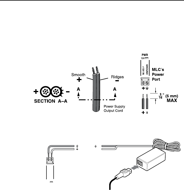
Power Connection
To connect the external 12 VDC power supply:
1. Strip the ends of the power supply wires as shown in the
diagram below.
2. Connect the stripped wires to the MLC's PWR port as
shown in the diagram below.
3. Connect the AC power cord between the power supply
and an AC power outlet.
MLC 104 Plus Series
Right Side Panel
12V
PWR
GROUND
+12V IN
Ground ( )
+12 VDC input
AC Power Cord
External
Power Supply
(12 VDC)