
Setup guide


Table Of Contents
- Front cover
- Safety Precautions
- Safety Precautions (Chinese) and FCC Class A Notice
- Table of Contents
- Ch. 1: Introduction
- Ch. 2: Hardware Setup
- Ch. 3: Software Setup
- Creating a Global Configurator Project File
- Configuring a New Device
- Step six: configure e‑mail server (IP models only)
- Step seven: configure e‑mail messages (IP models only)
- Step eight: configure contacts (IP models only)
- Step nine: assign serial device drivers
- Step ten: assign IR drivers
- Step eleven: configure the front panel
- Step twelve: configure associated control modules
- Step thirteen: create a shutdown schedule
- Step fourteen: create a lamp hour notification (IP models only)
- Step fifteen: create a disconnect notification (IP models only)
- Step sixteen: build the Global Configurator file
- Step seventeen: upload the Global Configurator file
- Step eighteen: launch GlobalViewer (IP models only)
- Testing the GlobalViewer pages
- Warranty
- Back cover:checklist and contact information
MLC 104 Plus Series • Hardware Setup
Hardware Setup
2-2
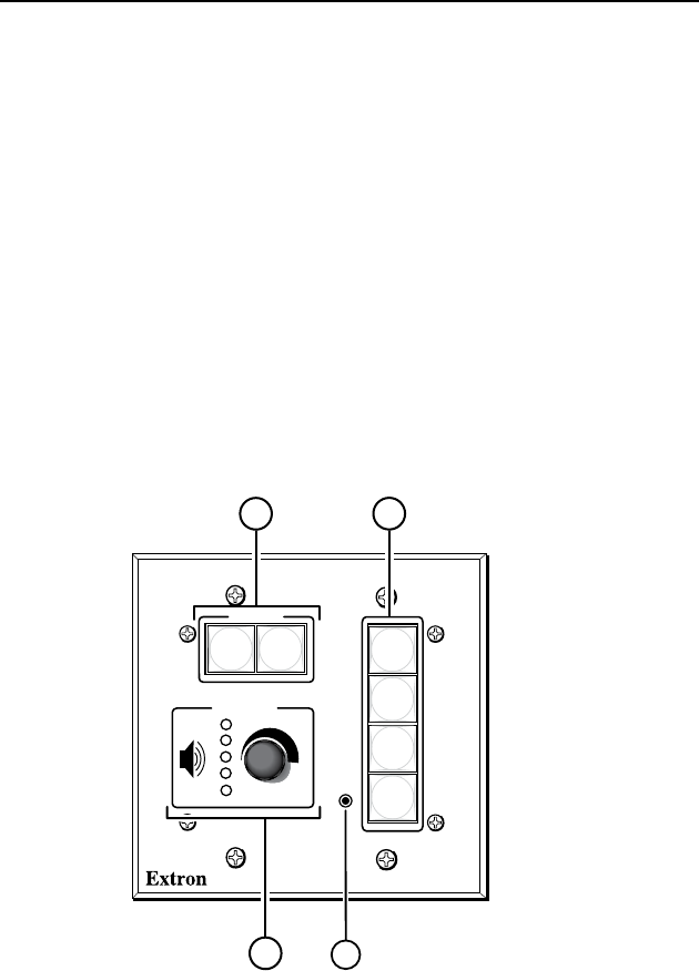
Front Panel
Front panel controls must be congured using the Global
Congurator application (described in chapter 3) before they
become functional.
a
Display On/Off buttons — Use to turn the connected display
device on and off.
b
Input selection buttons — Use to select the desired audio and
video input to the display device. Buttons light and remain lit
when selected.
c
Volume knob and LEDs — Use this knob to adjust the audio
volume. LEDs provide a visual indication of the current volume
level.
d
Front panel Config port — A 2.5 mm mini stereo jack provides
an RS-232 connection for conguration and control. Use Extron
conguration cable part #70-335-01 (9-pin D female to 2.5 mm
TRS) to connect a control PC to this port.
CONFIG
DISPLAY
VOLUME
MLC 104 IP PLUS
ON
VCR
DVD
PC
OFF
1
2
3
4
MLC 104 IP Plus
Front Panel
4
2
1
3