
Owner's manual


Chapter 2 • FPC 1000 Front Panel Controller • Installation
Extron • Matrix 3200/6400 Series Switchers • FPC 1000 • User’s Manual
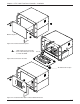
Basic Module Enclosure (BME)
Blank front panel
Figure 2-2a. Remove the blank panel.
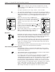
___ High voltage is present on the
back of the FPC panel as well
as inside the BME.
Figure 2-2b. Connect the RJ cable.
Figure 2-2c. Install the FPC 1000 in a Basic Module Enclosure
2-2
H
I
G
H
V
O
L
T
A
G
E
C
A
U
T
I
O
N
RJ Cable
H
I
G
H
V
O
L
T
A
G
E
C
A
U
T
I
O
N
Fuse
P
O
W
E
R
S
U
P
P
L
IE
S
C
O
M
M
U
N
IC
A
T
I
O
N
S
P
R
IM
A
R
Y
T
X
R
S
2
3
2
B
M
E
R
E
M
O
T
E
S
Y
S
T
E
M
S
T
A
T
U
S
R
E
D
U
N
D
A
N
T
R
X
D
I
A
G
N
O
S
T
I
C
S
+
V
-
V
R
G
B
M
U
T
E
A
U
D
I
O
M
U
T
E
________ Do NOT touch IC chips.