RGB MUTE AUDIO MUTE FPC-1000 POWER SUPPLIES -V +V PRIMARY REDUNDANT COMMUNICATIONS RS232 BME REMOTE SYSTEM STATUS TX MATRIX 6400 RX WIDEBAND VIDEO DIAGNOSTICS POWER SUPPLIES -V +V PRIMARY REDUNDANT COMMUNICATIONS RS232 BME REMOTE SYSTEM STATUS TX MATRIX 6400 RX WIDEBAND VIDEO DIAGNOSTICS POWER SUPPLIES -V +V PRIMARY REDUNDANT COMMUNICATIONS RS232 BME REMOTE SYSTEM STATUS TX MATRIX 6400 RX WIDEBAND VIDEO DIAGNOSTICS POWER SUPPLIES -V +V PRIMARY REDUNDANT COMMUNICATIONS RS232
Precautions Safety Instructions • English This symbol is intended to alert the user of important operating and maintenance (servicing) instructions in the literature provided with the equipment. This symbol is intended to alert the user of the presence of uninsulated dangerous voltage within the product's enclosure that may present a risk of electric shock. Warning Power sources • This equipment should be operated only from the power source indicated on the product.
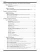
Contents Chapter 1 - Introduction and Features • FPC 1000 Front Panel Controller What is an FPC 1000? ....................................................................................................................... 1-1 Matrix 3200/6400 Series System Modules ......................................................................................... 1-1 FPC 1000 Features ............................................................................................................... 1-2 Specifications ...
Contents Figure 3-15. Misc/System Reset menu (shown with Factory Default selected) ......................... 3-16 Figure 3-16. Terminal Mode display of RS-232 dialog – example of a Tie command. ................ 3-17 Figure 3-17. Status/Remote menu showing MKP/MCP 1000s and their status. ........................ 3-18 Figure 3-18. Error screen showing message, category and number .........................................
Matrix 3200/6400 Series Front Panel Controller User’s Manual 1 Chapter One Introduction to the FPC 1000 What is a an FPC 1000? Matrix 3200/6400 Series System Modules Extron • Matrix 3200/6400 Series Switchers • FPC 1000 • User’s Manual Features
Introduction and Features • FPC 1000 Front Panel Controller • Chapter 1 What is an FPC 1000? The FPC 1000 is an optional Front Panel Controller designed to operate as part of Extron’s Matrix 3200/6400 Series Switching system. In most installations, RS-232 program control will be used because it is more powerful and complete. RS-232 control can be from a PC using Extron’s Windows® control software, or from a touch screen or any other controlling device capable of generating the proper commands.
Chapter 1 • FPC 1000 Front Panel Controller • Introduction and Features FPC 1000 Features Modular Design The modular design of the Matrix 3200/6400 Series switchers allows users the flexibility of purchasing only the modules required. In some systems, an FPC 1000 may not be needed. Panel Mount The Matrix 3200/6400 Series BMEs can be rack-mounted in any conventional 19" rack. The FPC 1000 mounts in place of the blank front panel in the master module (BME #0).
Introduction and Features • FPC 1000 Front Panel Controller • Chapter 1 Specifications The FPC 1000 is built in two sizes, one to fit in a 5U enclosure and one for a 7U enclosure. Otherwise, appearance and operation are the same. Each version is made up of a metal panel with an LCD display, 12 buttons and a knob. There are two tabs that hold the bottom in place and two 1/4-turn captive screws to hold the top in place. The slots in the screws can accommodate a screwdriver or a small coin.
Chapter 1 • FPC 1000 Front Panel Controller • Introduction and Features Matrix 3200/6400 Series Front Panel Controller User’s Manual 2 Chapter Two Installing the FPC 1000 Install Procedure Extron • Matrix 3200/6400 Series Switchers • FPC 1000 • User’s Manual
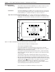
Installation • FPC 1000 Front Panel Controller • Chapter 2 The FPC 1000 offers local control at the switcher because it mounts as a front panel on the master BME (Basic Module Enclosure), as shown in Figure 2-1. In a system with more than one BME, the FPC 1000 must be installed in the master unit (address 0). Figure 2-1. An FPC 1000 mounted in a Matrix 3200/6400 Series Switcher BME Installing the FPC 1000 If the FPC 1000 was ordered with the Matrix 3200/6400 Series system, it will already be mounted.
Chapter 2 • FPC 1000 Front Panel Controller • Installation Basic Module Enclosure (BME) NOITUAC Figure 2-2a. Remove the blank panel. EGATLOV HGIH Blank front panel Fuse EGATLOV HGIH RJ Cable NOITUAC ___ High voltage is present on the back of the FPC panel as well as inside the BME. PO WE +V R SU PP LIE -V S PR IMA RY RE DU ND AN T TX RX RS COMM 232 UN ICA BM TIONS E DIA GN OS TIC S RE MO TE SY STE STA M TU S Figure 2-2b. Connect the RJ cable. ________ Do NOT touch IC chips.
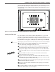
Installation • FPC 1000 Front Panel Controller • Chapter 2 RG MU B TE AU D MU IO TE PO WER +V SU PP LIES -V PR RE IM AR Y DU ND AN T TX RS CO 23 2 MM OST UN ICAT BM IONS E RE RX DIA GN ICS MO TE SY ST ST EM AT US Figure 2-3. The FPC 1000 shown mounted in a Matrix 3200/6400 Series Basic Module Enclosure With the FPC 1000 in place, apply power to the system. Go to Chapter 3 for FPC 1000 operation.
Matrix 3200/6400 Series Front Panel Controller User’s Manual 3 Chapter Three Using the FPC 1000 Front Panel Operation - Menu Functions How to Use the Menus and Panel Buttons Diagnostic LEDs FPC 1000 Menus (status, adjustments, resets) Error Screens
Using the FPC 1000 Front Panel Controller • Chapter 3 Front Panel Operation – menu functions The Front Panel Controller uses a 320 by 240 pixel LCD display with a set of six buttons above and a six below the display. Across the top of the screen is a title bar with menu names, each name aligns with one of the upper panel buttons. The top corner buttons are used to scroll the menu titles. Only four of eight possible menu names are displayed in the title bar at one time.
Chapter 3 • Using the FPC 1000 Front Panel Controller How to Use the Menus and Panel Buttons _______ Press any menu title button at any time to “escape” without making changes. Use menu selections with “soft” buttons. Descriptive menu title ○ ○ ○ ○ ○ ○ ○ ○ ○ ○ ○ ○ ○ ○ ○ ○ ○ ○ ○ ○ Because the buttons are dynamically reassigned to the title or option that appears next to it, they are called “soft” buttons. Instruction message appears here.
Using the FPC 1000 Front Panel Controller • Chapter 3 Instant Mute/Unmute Front Panel Controls Instant RGB Mute/Unmute – This button allows all RGB video outputs to be muted independent of any programmed muting. Press once and the LED lights to indicate that all RGB outputs are muted. Press the button again to restore the previous mute status. For example, if outputs 2, 29 and 35 were already muted, turning this RGB Mute function Off will unmute all except those three outputs.
Chapter 3 • Using the FPC 1000 Front Panel Controller System Status Menu This menu displays the configuration information and status for each BME (Basic Module Enclosure) in the system, as illustrated in the screen in Figure 3-4. It is only for viewing Status and not for changing it. Press any menu title button at any time to “escape” without making changes. To get here from the Main Menu, press: • Status Figure 3-4.
Using the FPC 1000 Front Panel Controller • Chapter 3 I/O Menu (by Output) Press any menu title button at any time to “escape” without making changes. To get here from the Main Menu, press: • I/O Displays vary depending upon system model and options. Instruction message appears here > Use option selections with buttons > Figure 3-5.
Chapter 3 • Using the FPC 1000 Front Panel Controller Name Use this button to change the name of the Input or Output that is currently selected. After pressing the Name button, the instruction message becomes: “Enter new name” The option soft buttons become: “Caps”, “Delete”, “Take” and “ESC” _________ The speed knob symbol will appear as a cursor above the character position of the name you are about to change. Use the knob to scroll through the characters (blank, special characters, 0-9 and A-Z).
Using the FPC 1000 Front Panel Controller • Chapter 3 Global Presets Menu Press any menu title button at any time to “escape” without making changes. To get here from the Main Menu, press: • Presets Displayed information may vary depending upon system model, options and setup. Instruction message appears here > Use option selections with buttons > Figure 3-6. Global Presets menu The 32 possible Global Preset numbers are displayed with their given names.
Chapter 3 • Using the FPC 1000 Front Panel Controller Room Presets Menu Press any menu title button at any time to “escape” without making changes. To get here from the Main Menu, press: • Presets • Room Instruction message appears here > Use option selections with buttons > Figure 3-7. Room Presets menu The Room Preset menu will show room #01, with its 10 presets listed below it and any virtual outputs to the right. Press Room# to select a different room with its presets and virtual outputs listed.
Using the FPC 1000 Front Panel Controller • Chapter 3 Triple-Action™ switching with adjustable delay (Wideband models) For seamless switching from one RGB input to another, an adjustable delay is available for each output. This allows the 3200/6400 systems to accommodate the switching characteristics of any display device. Those systems with RGBS or RGBHV video use Extron’s Triple-Action Switching for smooth transitions when switching from the image of one input source to another.
Chapter 3 • Using the FPC 1000 Front Panel Controller Delay Menu (for Triple-Action™ Switching) Press any menu title button at any time to “escape” without making changes. To get here from the Main Menu, press: • Delay Instruction message appears here > Use option selections with buttons > Figure 3-9. Delay menu (not available with composite or S-video) As explained on Page 3-9, the 3200/6400 Wideband Matrix systems have TripleAction Switching.
Using the FPC 1000 Front Panel Controller • Chapter 3 A/V Mute Menu Press any menu title button at any time to “escape” without making changes. Audio Mute/Unmute Instruction message appears here > Use option selections with buttons > Figure 3-10. A/V Mute menu, with RGB and Audio Muted for Output 01. ________ Use the speed knob or the scroll buttons to select the output to be muted or unmuted. The A/V Mute screen above shows examples of muted and not muted (unmuted) conditions on the left.
Chapter 3 • Using the FPC 1000 Front Panel Controller Audio Menu (by Input) Press any menu title button at any time to “escape” without making changes. To get here from the Main Menu, press: • Audio Instruction message appears here > Use option selections with buttons > Figure 3-11. Audio Gain/Attenuation menu This menu is used to display and adjust the gain or attenuation of each audio input. The range is from +9dB to -15dB.
Using the FPC 1000 Front Panel Controller • Chapter 3 Misc Menu Press any menu title button at any time to “escape” without making changes. System Reset Follow instructions for selected item. Instruction message appears here > Use option selections with buttons > Figure 3-12. Misc menu (shown with System Reset selected) Use the scroll buttons or the speed knob to select one of the four options from this menu. This example shows System Resets highlighted.
Chapter 3 • Using the FPC 1000 Front Panel Controller Misc Menu – LCD Adjust Press any menu title button at any time to “escape” without making changes. To get here from the Main Menu, press: • Misc • LCD Adjustments The information above the adjustment bar changes with each operation. > Instruction message appears here > Use option selections with buttons > Figure 3-13.
Using the FPC 1000 Front Panel Controller • Chapter 3 Misc Menu – Security Press any menu title button at any time to “escape” without making changes. To get here from the Main Menu, press: • Misc • Security Lockout Instruction message appears here > Use option selections with buttons > Figure 3-14.
Chapter 3 • Using the FPC 1000 Front Panel Controller Misc Menu – Resets Press any menu title button at any time to “escape” without making changes. To get here from the Main Menu, press: • Misc • System Resets Instruction message appears here > Use option selections with buttons > Figure 3-15. Misc/System Reset menu (shown with Factory Default selected) The items that appear in this menu may not be the same on your system.
Using the FPC 1000 Front Panel Controller • Chapter 3 Status Menu – Terminal Mode To get here from the Main Menu, press: Status • Terminal Terminal mode allows the LCD display to monitor RS-232 activity. The function buttons at the bottom of the screen are: Clear, Pause/Resume, Hex/ASCII and ESC. There is a scroll bar along the left side of the screen, with an indicator that moves upward as more data scrolls onto the display. RX precedes information received from the host.
Chapter 3 • Using the FPC 1000 Front Panel Controller Status Menu – MKP Mode The Remote button displays information about the remote keypads and panels. The example in Figure 3-17 shows the address, mode, configuration and currently selected input number for each MKP/MCP 1000 on the system. Address = This is the number programmed into that MKP 1000 or MCP 1000. Mode = Each MKP 1000 or MCP 1000 is programmed to one of 3 modes: Output, Room Preset or Global.
Using the FPC 1000 Front Panel Controller • Chapter 3 Error Screens If an error occurs, the FPC 1000 returns to the Main menu display and flashes a message in the center of the screen, similar to the one in Figure 3-18. Figure 3-18. Error screen showing message, category and number The first line is the error message “Communications Failure”. The next line gives a category (in this case, “Status”) and a number. _______ Should an error occur, write this information down and call Extron support.
FCC Class A Notice Note: This equipment has been tested and found to comply with the limits for a Class A digital device, pursuant to part 15 of the FCC Rules. These limits are designed to provide reasonable protection against harmful interference when the equipment is operated in a commercial environment. This equipment generates, uses and can radiate radio frequency energy and, if not installed and used in accordance with the instruction manual, may cause harmful interference to radio communications.
www.extron.com Extron Electronics, USA Extron Electronics, Europe Extron Electronics, Asia Extron Electronics, Japan 1230 South Lewis Street Anaheim, CA 92805 USA 714.491.1500 Fax 714.491.1517 Beeldschermweg 6C 3821 AH Amersfoort The Netherlands +31.33.453.4040 Fax +31.33.453.4050 135 Joo Seng Road, #04-01 PM Industrial Building Singapore 368363 +65.6383.4400 Fax +65.6383.4664 Daisan DMJ Building 6F 3-9-1 Kudan Minami Chiyoda-ku, Tokyo 102-0074 Japan +81.3.3511.7655 Fax +81.3.3511.