Matrix 3200 and 6400 Series Wideband Video/Sync Switcher 68-355-05 Rev.
Precautions Safety Instructions • English Warning This symbol is intended to alert the user of important operating and maintenance (servicing) instructions in the literature provided with the equipment. Power sources • This equipment should be operated only from the power source indicated on the product. This equipment is intended to be used with a main power system with a grounded (neutral) conductor. The third (grounding) pin is a safety feature, do not attempt to bypass or disable it.
FCC Class A Notice This equipment has been tested and found to comply with the limits for a Class A digital device, pursuant to part 15 of the FCC Rules. Operation is subject to the following two conditions: (1) this device may not cause harmful interference, and (2) this device must accept any interference received, including interference that may cause undesired operation.
Contents Chapter 1 - Introduction to the Matrix Wideband Video Switchers What is a Matrix Wideband Video Switcher? ..................................................................................... 1-1 Features ...................................................................................................................................... 1-1 Feature Descriptions ...................................................................................................................
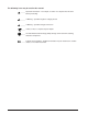
The following icons may be used in this manual: ______ Important information – for example, an action or a step that must be done before proceeding. ______ A Warning – possible dangerous voltage present. ______ A Warning – possible damage could occur. ____ A Note, a Hint, or a Tip that may be helpful. _____ Possible Electrostatic Discharge (ESD) damage could result from touching electronic components. _____ Indicates word definitions.
Matrix 3200 & 6400 Wideband Video/Sync Switchers 1 Chapter One Introduction to the Matrix 3200 & 6400 Wideband Video/Sync Switchers What is a Matrix Wideband Video Switcher? Features Specifications
Chapter 1 • Introduction to the Matrix 3200 & 6400 Wideband Video/Sync Switchers What is a Matrix Wideband Video Switcher? The Wideband Video Switcher is a 230 MHz bandwidth high resolution matrix switcher. It is available in a rack-mountable 5U (Matrix 3200) or 7U high (Matrix 6400) metal enclosure with internal universal switching power supply. A single Matrix 6400 will support up to 21x21 RGB matrix switching.
Chapter 1 • Introduction to the Matrix 3200 & 6400 Wideband Video/Sync Switchers Feature Descriptions Video Formats supported: RGBHV – RGB video with separate horizontal and vertical sync RGBS – RGB video with composite sync RGsB – RGB video with sync on green Virtual Control – Logical assignment of physical Input/Output connector. Microprocessor Control – A Microprocessor enables the Matrix Wideband Video switcher to be programmed from a host system, or from the optional Front Panel Controller (FPC 1000).
Chapter 1 • Introduction to the Matrix 3200 & 6400 Wideband Video/Sync Switchers Matrix 3200 & 6400 Wideband Video/Sync System Overview A Matrix 3200/6400 system may consist of 1 - 6 BMEs (Basic Module Enclosures). The user’s current and future video and audio switching requirements will determine the size and configuration of the system.
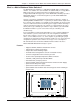
Chapter 1 • Introduction to the Matrix 3200 & 6400 Wideband Video/Sync Switchers Figure 1-4.A A 21x21x3 Virtualized Matrix 6400 Wideband Video module Figure 1-4.
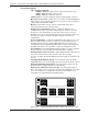
Chapter 1 • Introduction to the Matrix 3200 & 6400 Wideband Video/Sync Switchers RGB MUTE Matrix 6400 Wideband Video Switcher (Front View) Shown with optional Front Panel Controller (FPC 1000) AUDIO MUTE FPC-1000 POWER SUPPLIES -V +V COMMUNICATIONS RS232 PRIMARY TX REDUNDANT RX BME MKP SYSTEM STATUS MATRIX 6400 WIDEBAND DIAGNOSTICS BME - 1 2 3 4 5 6 7 9 10 11 13 14 15 INPUTS 17 18 19 20 8 21 22 23 24 12 25 26 25 28 16 29 30 31 32 4 + ADDRESS ANAHEIM, CA M
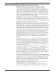
Chapter 1 • Introduction to the Matrix 3200 & 6400 Wideband Video/Sync Switchers Matrix 6400 Sync (Front View) POWER SUPPLIES -V +V COMMUNICATIONS RS232 PRIMARY TX REDUNDANT RX SYSTEM STATUS BME MATRIX 6400 SYNC DIAGNOSTICS BME - 1 2 3 4 5 6 7 9 10 11 13 14 15 INPUTS 17 18 19 20 8 21 22 23 24 12 25 26 25 28 16 29 30 31 32 4 + ADDRESS ANAHEIM, CA MADE IN USA A INPUTS 1 - 16 B 75 OHM C 510 OHM E A B 1 MKP COMM.
Chapter 1 • Introduction to the Matrix 3200 & 6400 Wideband Video/Sync Switchers Matrix 3200 Wideband Video Switcher (Front View) Shown with optional Front Panel Controller RGB MUTE AUDIO MUTE FPC-1000 POWER SUPPLIES -V +V PRIMARY REDUNDANT SYSTEM STATUS COMMUNICATIONS RS232 BME REMOTE TX MATRIX 3200 RX WIDEBAND DIAGNOSTICS BME - 4 + ADDRESS A INPUTS B D E A B MKP COMM.
Chapter 1 • Introduction to the Matrix 3200 & 6400 Wideband Video/Sync Switchers BME - 4 + ADDRESS A INPUTS B D E A B MKP COMM. C 1 2 3 4 17 18 19 20 5 6 7 9 10 11 8 21 22 23 24 12 25 26 25 13 14 15 28 16 29 30 31 32 C D ANAHEIM, CA MADE IN USA RS232/RS422 E Matrix 3200 Sync (Rear View) BME COMM. INPUTS 1 - 16 75 OHM 510 OHM 1 100-240V 0.5A MAX 50/60Hz AC POWER INPUT FUSE: 250V 5.
Chapter 1 • Introduction to the Matrix 3200 & 6400 Wideband Video/Sync Switchers Impedance ................................. Return loss ................................. DC offset .................................... Switching type ............................ Slew rate .................................... 75 ohms -25 dB to input section up to 50 MHz ±10 mV typical with input at 0 offset Triple-Action™ >200 V/ms Sync — sync BME Input and output types ................ Sync connectors .....................
Matrix 3200 & 6400 Wideband Video/Sync Switchers 2 Chapter Two Installing the Matrix 3200/6400 Wideband Video Switchers Installing BMEs Installing the Software BME Cabling
Chapter 2 • Installing the Matrix 3200/6400 Wideband Video Switchers Matrix 3200 & 6400 Wideband Video/Sync System Installation Extron recommends that the following steps be done in the order listed to install a Matrix 3200 & 6400 Wideband Video/Sync System. 1. 2. 3. 4. 5. 6. 7. 8. 9. Installing BME(s). (Page 2-1) Set the BME address numbers (0 - 5). (Page 2-2) Connect the BME COMM interconnecting cable(s). (Page 2-2) Connect the RS-232/RS-422 cable to BME #0’s serial port.
Chapter 2 • Installing the Matrix 3200/6400 Wideband Video Switchers 2. Setting BME Addresses Each BME must be set to a unique address of 0 - 5 using a push-button switch located on the rear panel (see Figure 2-2.B, Item 1). BME #0 will be the Main Controller and may be any module except the Sync module. 3.
Chapter 2 • Installing the Matrix 3200/6400 Wideband Video Switchers 6A. BME Power-Up Verification All BMEs have the Diagnostics LEDs shown in Figure 2-3.A. The normal state of the LEDs after power-up is Primary +V and -V LEDs ON. If the BME includes redundant power supplies, the Redundant +V and -V LEDs will also be ON. If the Primary power supply fails, its LEDs will be OFF and the Redundant LEDs will blink.
Chapter 2 • Installing the Matrix 3200/6400 Wideband Video Switchers 3. Scroll to the desired program and click Install. 4. Follow the on-screen instructions. By default, the Windows installation of the Virtualization/Control Program creates a C:\ Mtrx6400 directory, and it places four the following two icons into a group folder named “Extron Electronics: • MATRIX 6400+12800 Control Program • MATRIX 6400+12800 Help 5.
Chapter 2 • Installing the Matrix 3200/6400 Wideband Video Switchers 9. System Video, Sync and Audio Cabling Using work-sheets and/or printouts from the Matrix 6400 System Virtualization/ Control Program, install video and sync cables as required. Figure 2-2.B shows the connectors for the optional MKP 1000 keypads.
Matrix 3200 & 6400 Wideband Video/Sync Switchers 3 Chapter Three Using the Matrix 3200/6400 System Virtualization/Control Software
Chapter 3 • Tutorial - Using the Matrix 3200/6400 System Virtualization/Control Software Extron’s Matrix 3200/6400 System Virtualization/Control Program The Matrix 3200/6400 System Virtualization/Control program communicates with the Extron Matrix 3200/6400 System through the RS-232/422 port on BME #0 (defaults to 9600 baud, 8 bit, 1 stop, no parity). The program is required to initially set the Virtualization and optional Room configurations for the system.
Chapter 3 • Tutorial - Using the Matrix 3200/6400 System Virtualization/Control Software does; it groups physical input connectors and physical output connectors together into Virtual Inputs and Virtual Outputs, each of which switches from 1 to 6 Virtual Planes. Let’s carry the S-Video example a step further using the 64 x 64 Video BME and a 64 x 64 Audio BME.
Chapter 3 • Tutorial - Using the Matrix 3200/6400 System Virtualization/Control Software • The program will communicate with the Matrix 3200/6400 System to determine its hardware configuration (type and size of each connected BME). It then reads the system’s settings (Ties, Presets, Virtual Map, etc.) and draws a graphical representation of the unit’s configuration and settings (Ties) on the Main screen (Figure 3-5.A & B). It also reads the MTRX6400.
Chapter 3 • Tutorial - Using the Matrix 3200/6400 System Virtualization/Control Software ↑FIGURE 3-4.A Extron • Matrix 3200/6400 Series • User’s Manual ↓FIGURE 3-4.
Chapter 3 • Tutorial - Using the Matrix 3200/6400 System Virtualization/Control Software ↑FIGURE 3-5.A Main Screen - Ties 3-5 ↓FIGURE 3-5.
Chapter 3 • Tutorial - Using the Matrix 3200/6400 System Virtualization/Control Software • If you wish to group certain virtual outputs together so that you may later create Room Presets, now would be a good time to Create ROOMS by clicking CONFIGURE|ROOM CONFIGURATION. • You can create a hard-copy document that shows all the details from the Virtual Map screen at any time by clicking the PRINT MAPS menu. The printed maps make a very handy wiring guide and will appear in color if using a color printer.
Chapter 3 • Tutorial - Using the Matrix 3200/6400 System Virtualization/Control Software • From the menu on the Main screen, click SYSTEM-CONFIG to show the Virtual Switch Virtual Map screen (Figure 3-4.A). From the Virtual Map screen menu, click CONFIGURE|ROOM CONFIGURE to show the Room Mapper screen (Figure 3-7.A). Associate a Virtual Output with a room number by using the mouse to drag the output circle to the list on the right side. You can remove a Virtual Output from a room by FIGURE 3-7.
Chapter 3 • Tutorial - Using the Matrix 3200/6400 System Virtualization/Control Software the right side of the screen will cause that configuration to be read from the Matrix and drawn on the screen. The displayed preset becomes the “Current configuration” by clicking the GO BUTTON. • You can Add and Erase Ties (edit) when in the “Current configuration”. These edits are made using the mouse in a drag and drop operation. To add a Tie, drag the input box and drop it on the desired output box (left to right).
Chapter 3 • Tutorial - Using the Matrix 3200/6400 System Virtualization/Control Software • A typical Emulation operation might consist of multiple editing sessions: • Session A (connected to a Matrix 3200/6400 System) • Session B (Emulation) use MTRX6400.INI as the first file (source) to edit the last save from the Matrix use JOB1107.MTX as the second file (destination) • Session C (Emulation) use JOB1107.MTX as the first file (source) to further edit the last Emulation save use JOB1107.
Chapter 3 • Tutorial - Using the Matrix 3200/6400 System Virtualization/Control Software How to SAVE and RESTORE the Matrix 3200/6400 Settings The FILE menu provides the following functions: • Save MATRIX settings as... (uploads *.MTX file from system) • Restore MATRIX settings from... (downloads *.MTX file to system) • Save This Session’s settings (uploads MTRX6400.INI file from unit) • Restore Last Session’s settings (downloads MTRX6400.
Notes
Matrix 3200 & 6400 Wideband Video/Sync Switchers 4 Chapter Four RS-232/RS-422 Programmer’s Guide Serial Communications Port Host to Switcher Series Instructions Commands and Responses Error Codes Switcher Initiated Messages
Chapter 4 • Programmer’s Guide Serial Communications Port If the Matrix Wideband Video Switcher is the Master BME (BME #0), its RS-232/RS-422 connector may be connected to the serial port output of a Host device such as a computer or control panel. Software control of the switcher is made possible by this connection. A Host serial port connection to the RS-232/ RS-422 connector of a Matrix Wideband Video Switcher is shown in Figure 4-1.
Chapter 4 • Programmer’s Guide Host to Switcher Communications The Matrix Wideband Video Switcher accepts both Simple Instruction Set and Advanced Instruction Set Commands through the RS-232/RS-422 port. Simple Instruction Set (SIS) commands may consist of one or more characters per command field and do not require any special characters to begin or end the command character sequence. Switcher responses to SIS commands all end with a carriage return and a line feed (CR/LF).
Chapter 4 • Programmer’s Guide COMMAND/RESPONSE TABLE = = = = = = = = = = = = = = = = = = = = = = , = Escape Symbol Definitions: 1 thru maximum number of inputs Ø thru maximum number of inputs (Input Ø = muted output) 1 thru maximum number of outputs BME number (Ø thru 5) Ø dB thru 9 dB (audio gain) 1 dB thru 15 dB (audio attenuation) Numerical Value –15 thru +9 1 thru maximum number of rooms [1Ø max.] Ø or 1 (Ø meaning off and 1 meaning on) Global preset # (Ø = current ties for system in view) [32 max.
Chapter 4 • Programmer’s Guide SETTING AUDIO GAIN COMMANDS Positive Attenuation SIMPLE INSTRUCTION SET COMMANDS (PAGE 2 OF 3) ASCII (HOST-SWITCHER) RESPONSE (SWITCHER-HOST) * G In •Aud Example 4*3G InØ4•Aud+Ø3 Example explanation: Set Audio Gain on Virtual Input 4 to 3 dB. * g In •Aud Increment Audio Level (up) {G In •Aud Decrement Audio Level (down) }G In •Aud Example 4}G InØ4•Aud+Ø2 Example explanation: (Decrement Audio Level on Virtual Input 4 - down 1 dB).
Chapter 4 • Programmer’s Guide LIST COMMANDS SIMPLE INSTRUCTION SET COMMANDS (PAGE 3 OF 3) ASCII (HOST-SWITCHER) RESPONSE (SWITCHER-HOST) List Remote Keypad LK Example response for LK command List Presets LP Example response for LP command ADDR#MODE ID# NAME USER INPUT ADDR#MODE 1 GLBL ID# ,ØØ , NAME USER INPUT ,Ø1 2 OUTP ,14 , ConfRm1 ,Ø5 5 OUTP ,15 , Security2 ,Ø5 64 ROOM ,1Ø , ConfRm2 ROOM# PRESET# ROOM# GL PRESET# NAME FOLLOW MODE Ø1 ,DailyConfig ,ALL GL 32 ,LunchCon
Chapter 4 • Programmer’s Guide ADVANCED INSTRUCTION SET AND SIMPLE INSTRUCTION SET COMMANDS (PAGE 1 OF 3) ASCII (HOST-SWITCHER) RESPONSE (SWITCHER-HOST) VIEW COMMANDS Audio Gain V/v G In ·Aud Example V15G In15•Aud-Ø6 Example explanation: Virtual Input 15 Audio Level is set to -6 dB.
Chapter 4 • Programmer’s Guide ADVANCED INSTRUCTION SET AND SIMPLE INSTRUCTION SET COMMANDS (PAGE 2 OF 3) ASCII (HOST-SWITCHER) RESPONSE (SWITCHER-HOST) VIEW COMMANDS Virtual Output MUTES VM • ••••• 1 2 Mut 64 Notes: 1. Start output is always Ø1 for Room PRESET, because room has max. of 16 outputs assigned. 2. All “VI” values in responses are 2 numeric characters (i.e. 12 or Ø3) or “na” indicating non-existant virtual outputs 3.
Chapter 4 • Programmer’s Guide ZAP CONFIGURATION COMMANDS ASCII (HOST-SWITCHER) RESPONSE (SWITCHER-HOST) Zap All Global presets & names zG ZapG Zap individual Global zT ZapT Zap All Room presets & names zP ZapP Zap individual Room Preset zT Zap All RGB Delay to Ø sec. zD ZapD Zap all Audio Gains to Ø dB.
Chapter 4 • Programmer’s Guide RECONFIG25 = Individual mute change RECONFIG26 = RGB->SYNC delay change RECONFIG34 = A global preset has been saved RECONFIG35 = A room preset has been saved RECONFIG36 = All RGB Sync Delays initialized (Zapped to Ø sec) RECONFIG37 = All Audio Levels initialized (Zapped to Ø dB) RECONFIG38 = All Mutes initialized (Zapped to UnMuted) RECONFIG4Ø = Global mute change RECONFIG41 = Power supply status changed RECONFIG99 = Entire System initialized (Master Reset) 4-9 Extron • Matr
Matrix 3200 & 6400 Wideband Video/Sync Switchers 5 Chapter Five Upgrades and Troubleshooting Upgrade and Troubleshooting Procedures Installing a Software Update (IC Chip) Swapping RS-232/RS-422 Ports Checking/Replacing Fuses
Chapter 5 • Upgrades and Troubleshooting Upgrade and Troubleshooting Procedures The following procedures may be done in the field. • Add Front Panel Controller (FPC 1000) - see Page 5-1. • Installing a Software Upgrade - see Page 5-3. • Swapping RS-232 / RS-422 Ports - see Page 5-4. • Troubleshooting a system problem - see Page 5-5. • Adding Video cards to a Matrix 6400 Wideband Switcher- see Page 5-7. • Adding Video cards to a Matrix 3200 Wideband Switcher- see Page 5-9.
Chapter 5 • Upgrades and Troubleshooting BME Internal Access Upgrades or repairs may require access to internal areas of a BME. Internal access for the 5U/7U high Sync BME requires removal of ten screws (see Figure 5-2.A) plus a ribbon cable allowing the front panel to be removed (if the Sync BME is rack mounted and the case has no underneath support, it must be removed from the rack before removing the front panel).
Chapter 5 • Upgrades and Troubleshooting Installing A Software Update To install a software update, IC U9 or U6 (or both) on the Main Control circuit card is replaced. If the system consists of multiple BMEs, the software IC(s) in each BME’s Main Control card may need to be updated. Use the following procedure to replace the IC(s). 1. Power the system OFF and unplug the AC power cord. 2. Remove the Access Panel (Front Panel if Sync BME). See Page 5-2. 3. Use the PLCC IC puller (Figure 5-3.
Chapter 5 • Upgrades and Troubleshooting Swapping RS-232 / RS-422 Ports Swapping RS-232/RS-422 ports involves moving a ribbon cable from one Main Control card connector to another. Ribbon Cable Connectors The ribbon cables used in the Matrix Wideband Video Switchers use a self-latching style receptacle. Figure 54.A shows how it operates. 1. Press each of the two tabs outward, this unlocks the receptacle and ejects the ribbon cable connector part way. Pull evenly on the ribbon cable connector to remove it.
Chapter 5 • Upgrades and Troubleshooting Troubleshooting a Matrix 3200/6400 System Problem All Matrix 3200/6400 BME front panels include LEDs at the bottom of the panel which are bracketed and labeled DIAGNOSTICS. These LEDs (Figure 5-6.A) indicate the current status of the BME power supplies, the RS232/BME/MKP1 Communications RX and TX lines, and the System Status. The following descriptions include normal/failure/status conditions for each LED.
Chapter 5 • Upgrades and Troubleshooting Checking/Replacing the BME External AC Input Fuse The AC power input cord plugs into the Power-Switch/Fuse assembly which is located on the rear panel in the lower left corner of the BME. To check/replace the external fuse, remove the power-cord and insert the tip of a small screwdriver blade into the fuse-holder slot (the fuse-holder is located just below the power-switch). Pry the fuse-holder out, it contains the AC input fuse plus a spare.
Chapter 5 • Upgrades and Troubleshooting Matrix 6400 Wideband Video Switcher Upgrade - Adding Video Circuit-Cards Upgrading a Matrix 6400 Video Switcher which has a matrix size smaller than 64x64 requires adding one or more video cards. Both Input and Output Video cards may be required as shown in Figure 5-7.A below. Page 5-8 describes how to determine how many of each card type is required to change from one matrix size to another and which connectors to plug the new cards into.
Chapter 5 • Upgrades and Troubleshooting JC5 JC6 JC7 JC8 19 20 J1 1 JC4 JC3 JC2 JC1 2 JD7 JD5 JD3 JD1 JD8 JD6 JD4 JD2 JC13 JC14 JC15 JC16 JC12 JC11 JC10 JC9 Determining Matrix 6400 Wideband Video BME Circuit Card Population The drawing above shows the layout of the input and output video circuit card connectors on the inside of the Matrix 6400 Wideband Video Switcher rear panel. The chart below shows the REQUIRED circuit card population for every possible matrix configuration.
Chapter 5 • Upgrades and Troubleshooting Matrix 3200 Wideband Video Switcher Upgrade - Adding Video Circuit-Cards Upgrading a Matrix 3200 Video Switcher which has a matrix size smaller than 32x32 requires adding one or more video cards. Both Input and Output Video cards may be required as shown in Figure 5-9.A below. Page 5-10 describes how to determine how many of each card type is required to change from one matrix size to another and which connectors to plug the new cards into.
Chapter 5 • Upgrades and Troubleshooting JD4 JC4 19 20 J1 JD3 JD2 JD1 JC2 JC3 JC1 1 2 Determining Matrix 3200 Wideband Video BME Circuit Card Population The drawing above shows the layout of the input and output video circuit card connectors on the inside of the Matrix 3200 Wideband Switcher rear panel. The chart below shows the REQUIRED circuit card population for every possible matrix configuration.
Chapter 5 • Upgrades and Troubleshooting Adding BME(s) to a Matrix 3200/6400 System Adding BME(s) to an existing Matrix 3200/6400 System involves doing most of the same steps as an initial installation. Extron recommends that the following steps be done in the order listed to add BME(s). 1. See Page 5-12 “Software Procedure – Before and After a Hardware Upgrade”. 2. Installing BME(s). Remove power before proceeding. (Page 5-11 below) 3. Set the BME address numbers (0 - 5). (Page 2-2) 4.
Chapter 5 • Upgrades and Troubleshooting Software Procedure – Before and After a Hardware Upgrade Prior to upgrading a Matrix 3200/6400 Wideband Video Switcher System, read the “Upgrade System – Software Procedure” below. The suggested procedure can save you a lot of time reconfiguring a system that is going to have a hardware upgrade installed. The procedure includes steps to be performed before and after the hardware upgrade.
Notes
Matrix 3200 & 6400 Wideband Video/Sync Switchers A Appendix A Reference Information Switcher Part Numbers Related Part Numbers BNC Cables Glossary of Terms Work-sheets
Appendix A • Reference Information Matrix 3200/6400 Series Part Numbers Part Numbers for Matrix 3200/6400 switchers use the following format: 60-25x-iofr where: x = 0 = Matrix 6400 Wideband x = 1 = Matrix 3200 Wideband x = 2 = Matrix 6400 Video x = 3 = Matrix 3200 Video x = 4 = Matrix 6400 Sync x = 5 = Matrix 3200 Sync x = 6 = Matrix 6400 Audio io = Inputs/Outputs (Matrix size). The i and the o are replaced by two characters which identify the exact size of the Matrix.
Appendix A • Reference Information Matrix 3200/6400 Series Part Numbers (continued from previous page) Extron Part Matrix 6400 Wideband Switcher Part # 60-250-iofr Two io (Inputs/Outputs) characters = table matrix size coordinate points. f = Front Panel Controller (FPC), 0 = No, 1 = Yes r = Redundant Power Supply (RPS), 0 = No, 1 = Yes Matrix 3200 Wideband Switcher 60-251-iofr Two io (Inputs/Outputs) characters = table matrix size coordinate points.
Appendix A • Reference Information Matrix 3200/6400 Series Part Numbers (continued from previous page) Extron Part FPC 1000 (Matrix 6400 Series) FPC 1000 (Matrix 3200 Series) MCP 1000M MKP 1000 (Gray) MKP 1000 (Black) MKP 1000 (White) Wideband input card, 8 inputs (1 card) Wideband input card, 16 inputs (2 cards) Wideband input card, 16 inputs (4 cards) Wideband output card, 8 outputs (1 card) Stereo audio input card, 8 inputs (1 card) Stereo audio output card, 8 outputs (1 card) Mono audio input card, 8 i
Appendix A • Reference Information Pre-cut Cables The MHR-4 BNC is used for RGBS cable runs and the MHR-5 BNC is used for RGBHV cable runs, but either type can also be used for composite video, S-Video or RGB with sync on green. All Extron MHR cables have male gender connectors on both ends. Also available is a plenum version of the MHR-5 BNC cabling. MHR-4 Mini High Resolution Cable MHR-4 BNC/25 (25'/7.5 meters) 26-210-04 MHR-4 BNC/35 (35'/10.6 meters) 26-210-12 MHR-4 BNC/50 (50 feet/15.
Appendix A • Reference Information Glossary of terms Following is a list of terms taken from Extron’s Glossary. AC – Alternating Current – Flow of electrons that changes direction alternately. ADA – Extron’s product designation for Analog Distribution Amplifier. AMPS – Amperes – A unit of measurement for current. Analog – Analogue – A continuous signal that takes time to make a transition from one level to another. Standard audio and video signals are analog.
Appendix A • Reference Information Component Video – Our color television system starts with three channels of information; Red, Green, & Blue (RGB). In the process of translating these channels to a single composite video signal they are often first converted to Y, R-Y, and B-Y. Both 3-channel systems, RGB and Y, R -Y, B -Y are component video signals. They are the components that eventually make up the composite video signal.
Appendix A • Reference Information High Impedance – Hi Z or High Z – In video, when the signal is not terminated locally and is going to another destination, where it will be terminated. In video, Hi Z is typically 10k ohms or greater. Horizontal Rate – Horizontal Frequency – The number of complete horizontal lines, including trace and retrace, scanned per second. Typically shown as a measure of kHz.
Appendix A • Reference Information Output – The product of an operation by a device going to some external destination, such as another device, a video screen, image or hard copy. PAL – Phase Alternate Line – The phase of the color carrier is alternated from line to line. It takes four full pictures for the color horizontal phase relationship to return to the reference point. This alternation helps cancel out phase errors, the reason the hue control is not needed on PAL TV sets.
Appendix A • Reference Information SECAM – Sequential Couleur Avec Memoiré – Translated as “Sequential Color with Memory”. A composite color transmission system that potentially eliminates the need for both a color and hue control on the monitor. One of the color difference signals is transmitted on one line and the second is transmitted on the second line. Memory is required to obtain both color difference signals for color decoding.
Appendix A • Reference Information Matrix 6400 Wideband Video Switcher Virtualization Work-sheet Extron • Matrix 3200/6400 Series • User’s Manual A-10
Appendix A • Reference Information Matrix 3200 Wideband Video Switcher Virtualization Work-sheet A-11 Extron • Matrix 3200/6400 Series • User’s Manual
Extron’s Warranty Extron Electronics warrants this product against defects in materials and workmanship for a period of three years from the date of purchase.
www.extron.com Extron Electronics, USA 1230 South Lewis Street Anaheim, CA 92805 800.633.9876 714.491.1500 FAX 714.491.1517 Extron Electronics, Europe Beeldschermweg 6C 3821 AH Amersfoort, The Netherlands +800.3987.6673 +31.33.453.4040 FAX +31.33.453.4050 Extron Electronics, Asia 135 Joo Seng Rd. #04-01 PM Industrial Bldg., Singapore 368363 +800.7339.8766 +65.6383.4400 FAX +65.6383.4664 © 2008 Extron Electronics. All rights reserved.