
User Guide User Manual
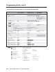
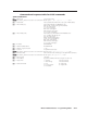
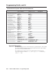
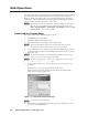
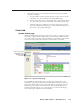
Table Of Contents
- Chapter 1 • Introduction
- Chapter 2 • Installation
- Chapter 3 • Virtualization/Control Software
- Explaining Virtual I/O Switching
- Virtualization/Control Program
- Creating a virtual I/O switching system (map)
- Reassigning virtual I/O connectors
- Creating rooms within the system
- Remote controlling the Matrix 12800 system
- Programming the matrix offline (emulate mode)
- Saving and restoring matrix settings
- Creating program byte strings
- Ethernet operation
- Windows buttons and drop boxes
- Special Characters
- Chapter 4 • Programming Guide
- Chapter 5 • Web Operations
- Chapter 6 • Upgrades and Maintenance
- Opening and Closing the Matrix Switcher
- Removing and Installing the Fan Assembly
- Removing and Installing the Power Supply Module
- Replacing the Fuse
- Removing and Cleaning the Filter
- Setting the DIP Switches
- Removing and Installing the Controller Card and Replacing the Firmware
- Removing and Installing the I/O Card and Setting the Audio Gain
- Troubleshooting
- Appendix A • Ethernet Connection
- Appendix B • Reference Information
- Inside rear cover: warranty
5-3
Matrix 12800 Switchers • Web Operations
PRELIMINARY
7. The switcher checks several possibilities, in the following order, and then
responds accordingly:
a. Does the address include a specific file name, such as 10.13.156.10/file_
name.html?Ifso,theswitcherdownloadsthatHTMLpage.
b. Istherealeinthememoryoftheswitcherthatisnamed“index.html”?
If so, the switcher downloads “index.html” as the default startup page.
c. If neither of the above conditions is true, the switcher downloads the
factory-installed default startup page, “nortxe_index.html” (figure 5-2),
also known as the System Status page.
Statu Tab
Ste Statu page
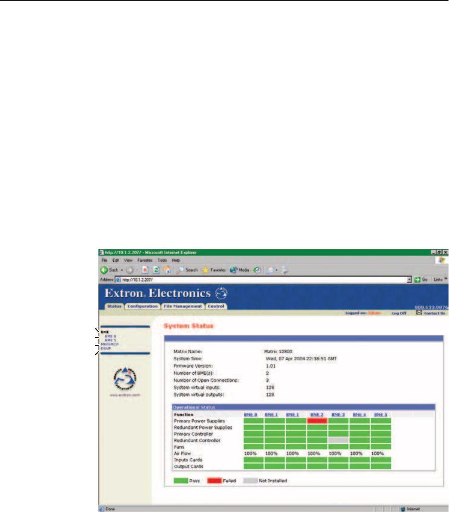
The Matrix 12800 System Status page (figure 5-2) provides an overall view of the
status of the complete matrix switcher system, encompassing all BMEs and their
active replaceable components. The status Web page automatically updates itself
every few seconds to reflect the latest status of the switcher components.
Refresh system status
Select DSVP
Individual BME status
MKP/MCP status
Figure 5-2 — System status page
For each BME, the System Status page shows the status of the primary and
redundant power supplies, the primary and redundant controller, the fans, the
input cards, and the output cards. Components that are operating properly are
indicated in green, failures are indicated in red, and components that are not
installed are indicated in gray. If a component fails or is removed, the display
shows the change in status the next time it updates.