
User Guide User Manual
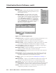
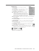
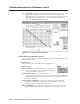
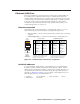
Table Of Contents
- Chapter 1 • Introduction
- Chapter 2 • Installation
- Chapter 3 • Virtualization/Control Software
- Explaining Virtual I/O Switching
- Virtualization/Control Program
- Creating a virtual I/O switching system (map)
- Reassigning virtual I/O connectors
- Creating rooms within the system
- Remote controlling the Matrix 12800 system
- Programming the matrix offline (emulate mode)
- Saving and restoring matrix settings
- Creating program byte strings
- Ethernet operation
- Windows buttons and drop boxes
- Special Characters
- Chapter 4 • Programming Guide
- Chapter 5 • Web Operations
- Chapter 6 • Upgrades and Maintenance
- Opening and Closing the Matrix Switcher
- Removing and Installing the Fan Assembly
- Removing and Installing the Power Supply Module
- Replacing the Fuse
- Removing and Cleaning the Filter
- Setting the DIP Switches
- Removing and Installing the Controller Card and Replacing the Firmware
- Removing and Installing the I/O Card and Setting the Audio Gain
- Troubleshooting
- Appendix A • Ethernet Connection
- Appendix B • Reference Information
- Inside rear cover: warranty
Matrix 12800 Switchers • Programming Guide
4-2
Prograing Guide
PRELIMINARY
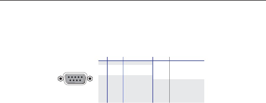
RS-232/RS-422 Port
The rear panel RS-232/RS-422 connectors (figure 4-1) of the matrix switcher BME 0
can be connected to the serial port output of a host device such as a computer
running the HyperTerminal utility or a control system. This connection makes
Simple Instruction Set (SIS) control of the switcher possible from the computer or
host via the RS-232/RS-422 link.
RS-232FunctionPin
1
2
3
4
5
6
7
8
9
—
TX
RX
—
Gnd
—
—
—
—
Not used
Transmit data
Receive data
Not used
Signal ground
Not used
Not used
Not used
Not used
RS-422 Function
TX+
TX-
RX+
RX-
Gnd
—
—
—
—
Transmit data (+)
Transmit data (-)
Receive data (+)
Receive data (-)
Signal ground
Not used
Not used
Not used
Not used
51
96
Female
Figure 4-1 — RS-232/RS-422 connector pin arrangement
N
The Matrix 12800 Switchers are factory configured for RS-232 control. To
use the switcher under RS-422 control, you must change an internal DIP
switch. See “Swapping the serial port protocol (RS-232/RS-422)” in chapter 6,
“Upgrades and Maintenance”, for details.
The default communications rate is 9600 baud. Baud rates of 19200, 38400, and
115200 are also available, see “Changing the serial port baud rate”, in chapter 6,
“Upgrades and Maintenance”. The protocol is 8-bit, 1 stop bit, no parity, and no
flow control.