
User Guide User Manual
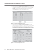
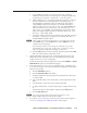
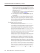
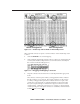
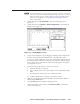
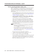
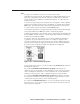
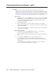
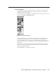
Table Of Contents
- Chapter 1 • Introduction
- Chapter 2 • Installation
- Chapter 3 • Virtualization/Control Software
- Explaining Virtual I/O Switching
- Virtualization/Control Program
- Creating a virtual I/O switching system (map)
- Reassigning virtual I/O connectors
- Creating rooms within the system
- Remote controlling the Matrix 12800 system
- Programming the matrix offline (emulate mode)
- Saving and restoring matrix settings
- Creating program byte strings
- Ethernet operation
- Windows buttons and drop boxes
- Special Characters
- Chapter 4 • Programming Guide
- Chapter 5 • Web Operations
- Chapter 6 • Upgrades and Maintenance
- Opening and Closing the Matrix Switcher
- Removing and Installing the Fan Assembly
- Removing and Installing the Power Supply Module
- Replacing the Fuse
- Removing and Cleaning the Filter
- Setting the DIP Switches
- Removing and Installing the Controller Card and Replacing the Firmware
- Removing and Installing the I/O Card and Setting the Audio Gain
- Troubleshooting
- Appendix A • Ethernet Connection
- Appendix B • Reference Information
- Inside rear cover: warranty
3-11
Matrix 12800 Switchers • Virtualization/Control Software
PRELIMINARY
Figure 3-6 — Virtual map and list fields of Virtual Map screen
Map an unused connector to replace a current connector on the Virtual Map screen
as follow:
1. Click the Edit Mode box to enable mapping.
2. Click and begin dragging the unused connector. When you start dragging the
connector, the Virtual I/O Map field moves down the screen to the entry for
the connector in the list field (figure 3-7).
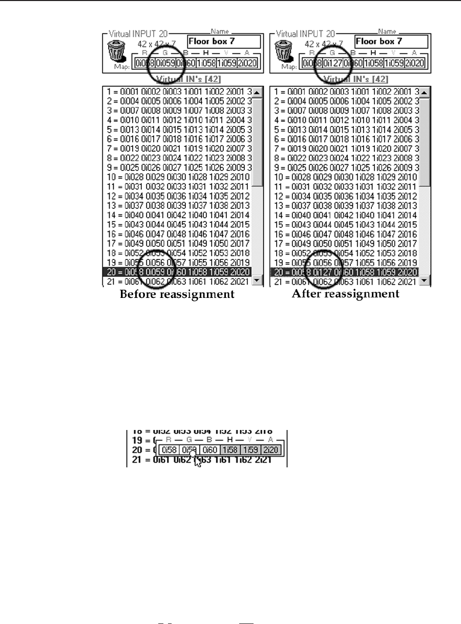
Figure 3-7 — Dragging and dropping a connector
3. Drop the connector into the Virtual Ins or Outs Map field in the appropriate
frame.
The connector on the map from which you dragged turns white to indicate
that the connector is now unused. The connector indicator for the location
to which you dragged turns pale blue to indicate that it is now part of the
virtual plane. The Virtual Ins or Outs Map field entry for the virtual plane
that you reassigned changes to reflect the new physical connector for that
virtual interface. On the After reassignment view of figure 3-6, the reassigned
virtual input 20 green video plane connector is coded 0i127, which translates
to BME 0, input connector 127.