
User Guide User Manual
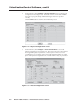
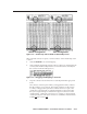
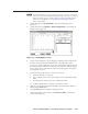
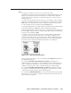
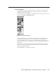
Table Of Contents
- Chapter 1 • Introduction
- Chapter 2 • Installation
- Chapter 3 • Virtualization/Control Software
- Explaining Virtual I/O Switching
- Virtualization/Control Program
- Creating a virtual I/O switching system (map)
- Reassigning virtual I/O connectors
- Creating rooms within the system
- Remote controlling the Matrix 12800 system
- Programming the matrix offline (emulate mode)
- Saving and restoring matrix settings
- Creating program byte strings
- Ethernet operation
- Windows buttons and drop boxes
- Special Characters
- Chapter 4 • Programming Guide
- Chapter 5 • Web Operations
- Chapter 6 • Upgrades and Maintenance
- Opening and Closing the Matrix Switcher
- Removing and Installing the Fan Assembly
- Removing and Installing the Power Supply Module
- Replacing the Fuse
- Removing and Cleaning the Filter
- Setting the DIP Switches
- Removing and Installing the Controller Card and Replacing the Firmware
- Removing and Installing the I/O Card and Setting the Audio Gain
- Troubleshooting
- Appendix A • Ethernet Connection
- Appendix B • Reference Information
- Inside rear cover: warranty
Virtualization/Control Software, cont’d
Matrix 12800 Switchers • Virtualization/Control Software
3-8
PRELIMINARY
5. On the menu bar, click Configure > Physical Switchers to show the Physical
Configuration screen (figure 3-4). Check this screen to ensure that all BMEs
were seen on program startup and that their type and size is reported
correctly.
Click the Close button to return to the Virtual Map screen.
Figure 3-4 — Physical Configuration screen
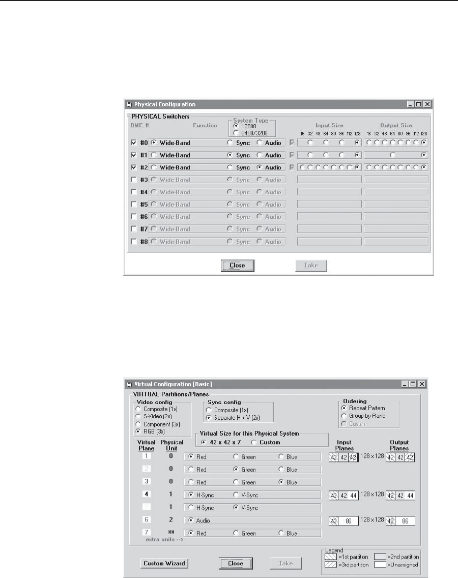
6. On the menu bar, click Configure > Virtual Switcher-Basic to show the
Virtual Configuration screen (figure 3-5). This screen shows how the software
has mapped the physical system into a virtual system. There are several
variables that you can change on this screen that affect the number of virtual
planes and inputs and outputs that are available and how they are presented.
Figure 3-5 — Virtual Configuration screen