
User Guide User Manual
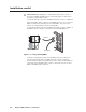
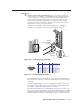
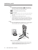


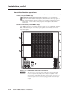
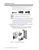
Table Of Contents
- Chapter 1 • Introduction
- Chapter 2 • Installation
- Chapter 3 • Virtualization/Control Software
- Explaining Virtual I/O Switching
- Virtualization/Control Program
- Creating a virtual I/O switching system (map)
- Reassigning virtual I/O connectors
- Creating rooms within the system
- Remote controlling the Matrix 12800 system
- Programming the matrix offline (emulate mode)
- Saving and restoring matrix settings
- Creating program byte strings
- Ethernet operation
- Windows buttons and drop boxes
- Special Characters
- Chapter 4 • Programming Guide
- Chapter 5 • Web Operations
- Chapter 6 • Upgrades and Maintenance
- Opening and Closing the Matrix Switcher
- Removing and Installing the Fan Assembly
- Removing and Installing the Power Supply Module
- Replacing the Fuse
- Removing and Cleaning the Filter
- Setting the DIP Switches
- Removing and Installing the Controller Card and Replacing the Firmware
- Removing and Installing the I/O Card and Setting the Audio Gain
- Troubleshooting
- Appendix A • Ethernet Connection
- Appendix B • Reference Information
- Inside rear cover: warranty
2-15
Matrix 12800 Switchers • Installation
PRELIMINARY
o
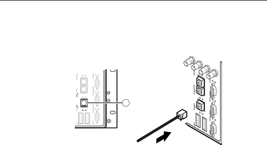
Ethernet port — For systems consisting of a single switcher or for BME 0
on a multi-BME system, if desired connect the Matrix 12800 either directly
to an FPC 5000 Front Panel Controller or to an Ethernet LAN via this RJ-45
connector (figure 2-14). If you are connecting to a LAN, you can still use an
FPC 5000 as one of the other nodes of the LAN.
BME COMM
IN OUT
FPC COMM
Tx
Rx
Tx
Rx
Tx
Rx
Tx
Rx
Tx
Rx
SECONDARY PRIMARY
RS 232/422 RS 232/422
ETHERNET
Tx
Rx
MCP/MKP COMM
A B C D E
15
SECONDARY
MCP/MKP COMM
ETHERNET
BME COMM
IN OUT
A B C D E
PRIMARY FPC COMM
Tx
Rx
Tx
Rx
Tx
Rx
Tx
Rx
Tx
Rx
Tx
Rx
RS 232/422 RS 232/422
80 96 112
128
Figure 2-14 — Connecting to the Ethernet
Cabling and RJ-45 connector wiring
It is vital that your Ethernet cables be the correct cables, and that they be properly
terminated with the correct pinout. Ethernet links use Category (CAT) 5e or CAT 6,
unshielded twisted pair (UTP) or shielded twisted pair (STP) cables, terminated
with RJ-45 connectors. Ethernet cables are limited to a length of 328 feet (100 m).
N
Do not use standard telephone cables. Telephone cables do not support Ethernet
or Fast Ethernet.
Do not stretch or bend cables. Transmission errors can occur.
The cable used depends on your network speed. The switcher supports both
10 Mbps (10Base-T — Ethernet) and 100 Mbps (100Base-T — Fast Ethernet),
half-duplex and full-duplex, Ethernet connections.
• 10Base-TEthernetrequiresCAT3UTPorSTPcableatminimum.
• 100Base-TFastEthernetrequiresCAT5eUTPorSTPcableatminimum.
The Ethernet cable can be terminated as a straight-through cable or a
crossover cable and must be properly terminated for your application
(figure 2-15, on the next page).
• Crossover cable — Direct connection between the computer and the
matrix switcher.
• Patch (straight) cable — Connection of the matrix switcher to an Ethernet
LAN.