
User Guide User Manual
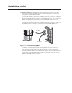
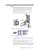
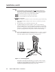
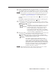
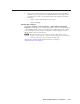
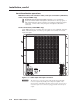
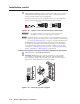
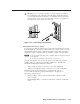
Table Of Contents
- Chapter 1 • Introduction
- Chapter 2 • Installation
- Chapter 3 • Virtualization/Control Software
- Explaining Virtual I/O Switching
- Virtualization/Control Program
- Creating a virtual I/O switching system (map)
- Reassigning virtual I/O connectors
- Creating rooms within the system
- Remote controlling the Matrix 12800 system
- Programming the matrix offline (emulate mode)
- Saving and restoring matrix settings
- Creating program byte strings
- Ethernet operation
- Windows buttons and drop boxes
- Special Characters
- Chapter 4 • Programming Guide
- Chapter 5 • Web Operations
- Chapter 6 • Upgrades and Maintenance
- Opening and Closing the Matrix Switcher
- Removing and Installing the Fan Assembly
- Removing and Installing the Power Supply Module
- Replacing the Fuse
- Removing and Cleaning the Filter
- Setting the DIP Switches
- Removing and Installing the Controller Card and Replacing the Firmware
- Removing and Installing the I/O Card and Setting the Audio Gain
- Troubleshooting
- Appendix A • Ethernet Connection
- Appendix B • Reference Information
- Inside rear cover: warranty
Intallation, cont’d
Matrix 12800 Switchers • Installation
2-12
PRELIMINARY
Pot-Virtualization operation
Wideband video, low reolution video, and nc connection (wideband,
video, and nc BME onl)
9
10
Wideband and sync input and output connectors — Use worksheets,
printouts from the Matrix 12800 System/Virtualization Control program, or
both to determine the virtual connection on each physical input and output
connection. Connect video and sync inputs and outputs to these BNC
connectors.
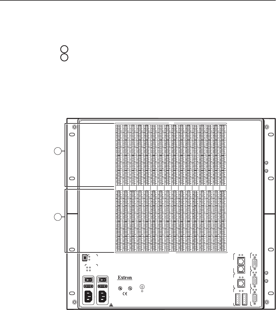
Audio connection (audio BME onl)
Audio BMEs (figure 2-9) are similar in most respects to sync, wideband, and video
BMEs, with the exception of 3.5 mm, 5-pole captive screw connectors for audio
input and output.
DISCONNECT BOTH POWER CORDS BEFORE SERVICING.
100-240V 5.0A MAX 50/60Hz FUSE 250V 5.0A T
100-240V 5.0A MAX 50/60Hz FUSE 250V 5.0A T
PRIMARY AC
POWER INPUT
POWER SUPPLIES
CPU STATUS
LISTED
1T23
I.T.E.
BME
PRIMARY
REDUNDANT
CAUTION
For protection against risk of
fire, replace only with same
type and rating of fuse.
PRIMARY
REDUNDANT
REDUNDANT AC
POWER INPUT
ANAHEIM, CA
MADE IN USA
+V -V
ADDRESS
4
-
+
SECONDARY
MCP/MKP COMM ETHERNET BME COMM
IN OUT
A B C D E
PRIMARY FPC COMM
Tx
Rx
Tx
Rx
Tx
Rx
Tx
Rx
Tx
Rx
Tx
Rx
RS 232/422 RS 232/422
INPUTS
OUTPUTS
1-8
9-16 17-24
25-32 33-40 41-48 49-56
57-64
65-72 73-80
81-88 89-96 97-104 105-112
113-120
121-128
12
11
Figure 2-9 — Audio input and output connectors
C
The captive screw connector can be inadvertently plugged partially
into one receptacle and partially into an adjacent receptacle. This
misconnection could damage the audio output circuits. Exercise care to
ensure the captive screw connector is plugged into the desired input or
output.