
User Guide User Manual
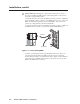
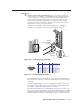

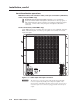
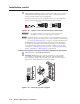
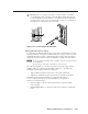
Table Of Contents
- Chapter 1 • Introduction
- Chapter 2 • Installation
- Chapter 3 • Virtualization/Control Software
- Explaining Virtual I/O Switching
- Virtualization/Control Program
- Creating a virtual I/O switching system (map)
- Reassigning virtual I/O connectors
- Creating rooms within the system
- Remote controlling the Matrix 12800 system
- Programming the matrix offline (emulate mode)
- Saving and restoring matrix settings
- Creating program byte strings
- Ethernet operation
- Windows buttons and drop boxes
- Special Characters
- Chapter 4 • Programming Guide
- Chapter 5 • Web Operations
- Chapter 6 • Upgrades and Maintenance
- Opening and Closing the Matrix Switcher
- Removing and Installing the Fan Assembly
- Removing and Installing the Power Supply Module
- Replacing the Fuse
- Removing and Cleaning the Filter
- Setting the DIP Switches
- Removing and Installing the Controller Card and Replacing the Firmware
- Removing and Installing the I/O Card and Setting the Audio Gain
- Troubleshooting
- Appendix A • Ethernet Connection
- Appendix B • Reference Information
- Inside rear cover: warranty
Intallation, cont’d
Matrix 12800 Switchers • Installation
2-8
PRELIMINARY
Ground
d
Ground terminal — If the power outlets do not provide connections to
the protective ground of the building, connect ground straps between this
terminal lug on all BMEs and a hard building ground. Secure the ground
straps with the nut and washer included with each BME.
N
You are responsible for providing the ground straps.
N
Some earlier BMEs do not have the ground terminal.
UL guidelines for ground
N
The equipment is intended to be used in a location having equipotential bonding.
1. The building installation shall provide a means for connection to protective
earth;and
2. Theequipmentistobeconnectedtothatmeans;and
3. A SERVICE PERSON shall check whether or not the socket-outlet from
which the equipment is to be powered provides a connection to the building
protective earth (ground). If not, the SERVICE PERSON shall arrange for the
installation of a PROTECTIVE EARTHING CONDUCTOR from the separate
protective earthing terminal to the protective earth wire in the building.
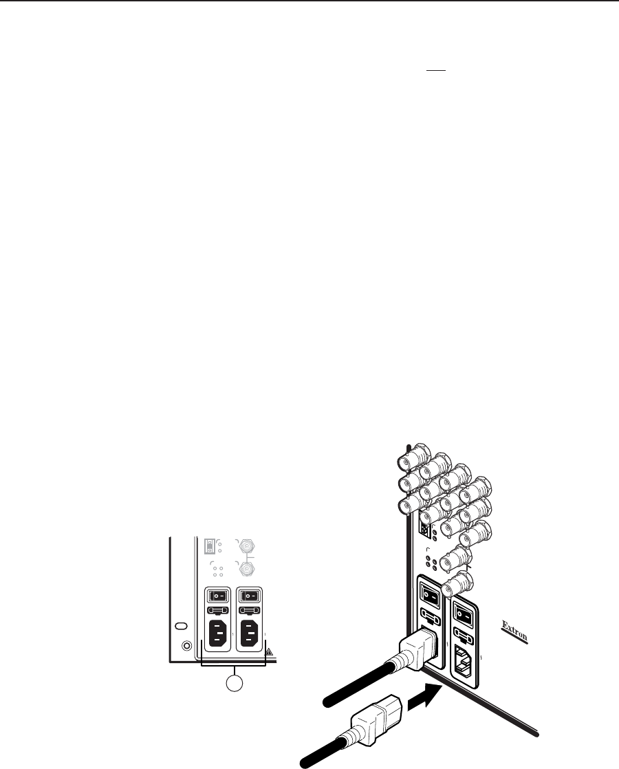
Power
e
Primary and Redundant AC Power Input connectors — Connect a standard
IEC power cord between the rear panel Primary AC Power Input connector
and a 100 to 240VAC, 50 Hz or 60 Hz power source (figure 2-6).
POWER SUPPLIES
CPU STATUS
BME
PRIMARY
REDUNDANT
PRIMARY
REDUNDANT
SYNC
+V -V
ADDRESS
4
-
+
IN
OUT
DISCONNECT BOTH POWER CORDS BEFORE SERVICING.
100-240V 5.0A MAX 50/60Hz FUSE 250V 5.0A T
100-240V 5.0A MAX 50/60Hz FUSE 250V 5.0A T
PRIMARY AC
POWER INPUT
REDUNDANT AC
POWER INPUT
5
BME
ADDRES
S
ANAHEIM, CA
MADE IN USA
4
For protection against r
isk of
fire, replace only with sam
e
type and rating of fuse
.
CAUTION
REDUNDANT AC
POWER INPUT
100-240V 0.5A MAX 50/60Hz
PRIMARY AC
POWER INPUT
100-240V 0.5A MAX 50/60Hz
PRIMARY
REDUNDANT
POWER SUPPLIES
+v -v
CPU STATUS
PRIMARY
REDUNDANT
SYNC
OUT
IN
Primary AC
Power Input
Redundant AC
Power Input
Figure 2-6 — Connecting power
If this BME is equipped with redundant power supplies A and B, connect a
second IEC power cord between the Redundant AC Power Input connector
and either an uninterruptible power source or a power source that is
completely independent from the primary power source.