
User Guide User Manual
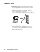
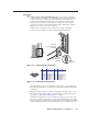
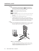
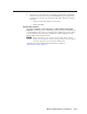
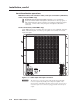
Table Of Contents
- Chapter 1 • Introduction
- Chapter 2 • Installation
- Chapter 3 • Virtualization/Control Software
- Explaining Virtual I/O Switching
- Virtualization/Control Program
- Creating a virtual I/O switching system (map)
- Reassigning virtual I/O connectors
- Creating rooms within the system
- Remote controlling the Matrix 12800 system
- Programming the matrix offline (emulate mode)
- Saving and restoring matrix settings
- Creating program byte strings
- Ethernet operation
- Windows buttons and drop boxes
- Special Characters
- Chapter 4 • Programming Guide
- Chapter 5 • Web Operations
- Chapter 6 • Upgrades and Maintenance
- Opening and Closing the Matrix Switcher
- Removing and Installing the Fan Assembly
- Removing and Installing the Power Supply Module
- Replacing the Fuse
- Removing and Cleaning the Filter
- Setting the DIP Switches
- Removing and Installing the Controller Card and Replacing the Firmware
- Removing and Installing the I/O Card and Setting the Audio Gain
- Troubleshooting
- Appendix A • Ethernet Connection
- Appendix B • Reference Information
- Inside rear cover: warranty
2-7
Matrix 12800 Switchers • Installation
PRELIMINARY
Serial port
c
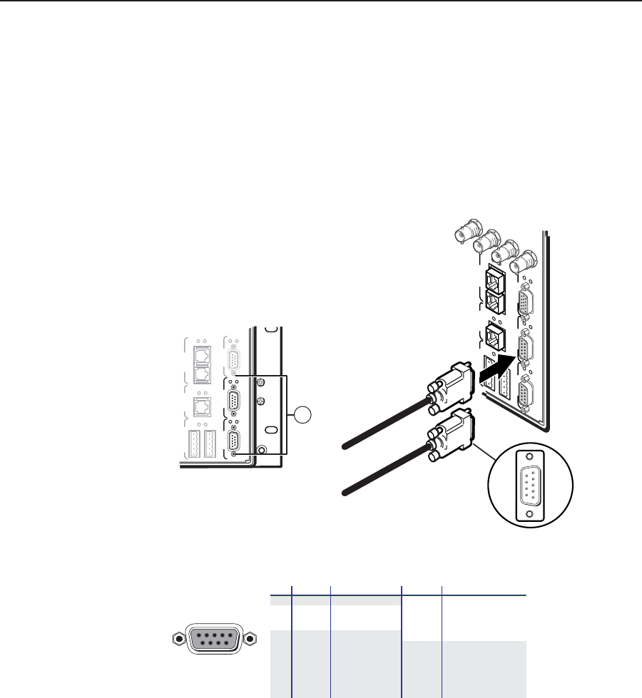
Primary and Secondary RS-232/RS-422 ports — For systems consisting of
a single switcher or for BME 0 on a multi-BME system, connect host devices
(such as computers or touch panel control systems) or MCP 1000 remote
control panels (see the MCP 1000 Remote Control Panel User Guide) to the
Primary and Secondary RS-232/RS-422 ports (figure 2-4). These 9-pin D
connectors provide for serial RS-232/RS-422 control of the matrix switcher.
Figure 2-5 shows how to wire the connectors.
Bothportsareconnectedtobothcontrollercircuitcards;aredundant
controller is not required to use the Secondary RS-232/RS-422 port.
MCP/MKP COMM ETHERNET BME COMM
IN OUT
A B C D E
FPC COMM
Tx
Rx
Tx
Rx
Tx
Rx
Tx
Rx
SECONDARY PRIMARY
Tx
Rx
Tx
Rx
RS 232/422 RS 232/422
3
SECONDARY
MCP/MKP COMM
ETHERNET
BME COMM
IN OUT
A B C D E
PRIMARY FPC COMM
Tx
Rx
Tx
Rx
Tx
Rx
Tx
Rx
Tx
Rx
Tx
Rx
RS 232/422 RS 232/422
80 96 112
128
To Secondary
Host System/Device
Serial Port
To Primary
Host System/Device
Serial Port
Male
Connector
1
5
6
9
Figure 2-4 — Connecting host controllers
RS-232FunctionPin
1
2
3
4
5
6
7
8
9
—
TX
RX
—
Gnd
—
—
—
—
Not used
Transmit data
Receive data
Not used
Signal ground
Not used
Not used
Not used
Not used
RS-422 Function
TX+
TX-
RX+
RX-
Gnd
—
—
—
—
Transmit data (+)
Transmit data (-)
Receive data (+)
Receive data (-)
Signal ground
Not used
Not used
Not used
Not used
51
96
Female
Figure 2-5 — RS-232/RS-422 port pinout
After the BMEs have been virtualized, the system can be controlled through
this connection using the PC or other host system that can generate the proper
commands.
The Matrix 12800 Switchers are factory configured for RS-232 control. To use
the switcher under RS-422 control, you must change an internal DIP switch.
See chapter 6, “Upgrades and Maintenance” for details.
The default communications rate is 9600 baud. Baud rates of 19.2, 38.4, and
115 are also available. See chapter 6, “Upgrades and Maintenance” for details.
If equipped with a redundant controller, the primary and redundant controllers
must be configured for the same communications protocol and transfer rates.