
User Guide User Manual
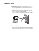
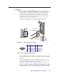
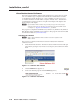
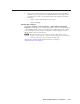
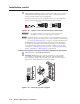
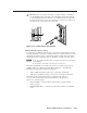
Table Of Contents
- Chapter 1 • Introduction
- Chapter 2 • Installation
- Chapter 3 • Virtualization/Control Software
- Explaining Virtual I/O Switching
- Virtualization/Control Program
- Creating a virtual I/O switching system (map)
- Reassigning virtual I/O connectors
- Creating rooms within the system
- Remote controlling the Matrix 12800 system
- Programming the matrix offline (emulate mode)
- Saving and restoring matrix settings
- Creating program byte strings
- Ethernet operation
- Windows buttons and drop boxes
- Special Characters
- Chapter 4 • Programming Guide
- Chapter 5 • Web Operations
- Chapter 6 • Upgrades and Maintenance
- Opening and Closing the Matrix Switcher
- Removing and Installing the Fan Assembly
- Removing and Installing the Power Supply Module
- Replacing the Fuse
- Removing and Cleaning the Filter
- Setting the DIP Switches
- Removing and Installing the Controller Card and Replacing the Firmware
- Removing and Installing the I/O Card and Setting the Audio Gain
- Troubleshooting
- Appendix A • Ethernet Connection
- Appendix B • Reference Information
- Inside rear cover: warranty
Intallation, cont’d
Matrix 12800 Switchers • Installation
2-6
PRELIMINARY
b
BME COMM interconnect ports — If the Matrix 12800 system consists of
more than one BME, the BMEs must be connected together in a daisy chain
using Extron-supplied RJ-45 cables.
Connect the first daisy chain from the BME Comm Out connector on BME 0 to
the nearest BME Comm In connector on the BME (figure 2-3). In a rack whose
BMEs are numbered sequentially, this would be BME 1. But, since not all
systems are configured alike, call this module BME n.
Connect the next RJ-45 cable from the BME Comm Out connector on BME n to
the BME Comm In connector on nearest unconnected BME (BME n+1) .
SECONDARY
MCP/MKP COMM ETHERNET
BME COMM
IN OUT
A B C D E
PRIMARY
FPC COMM
Tx
Rx
Tx
Rx
Tx
Rx
Tx
Rx
Tx
Rx
Tx
Rx
RS 232/422 RS 232/422
Rx
2
SECONDARY
MCP/MKP COMM
ETHERNET
BME COMM
IN OUT
A B C D E
PRIMARY FPC COMM
Tx
Rx
Tx
Rx
Tx
Rx
Tx
Rx
Tx
Rx
Tx
Rx
RS 232/422 RS 232/422
80 96 112
128
From BME 0
To BME 2
BME 1
Figure 2-3 — Daisy-chaining BMEs
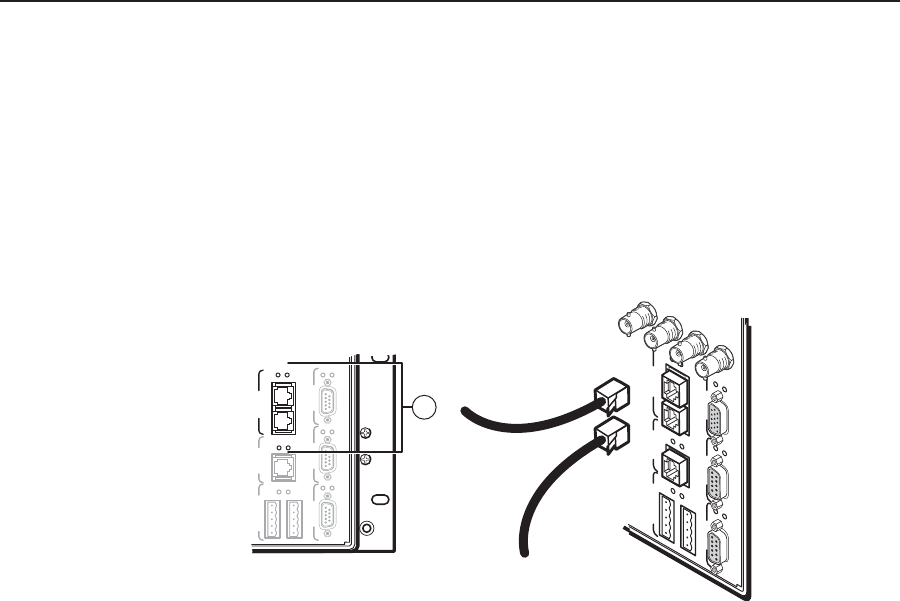
Continue connecting RJ-45 cables from the BME Comm Out connector on
each daisy-chained module to the BME Comm In connector on the next
module until all modules are included in the chain. When all of the BMEs are
connected, each of the BMEs in the system is connected to at least one other
BME via the BME Comm connectors.