
User Guide User Manual
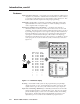
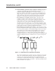
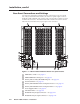
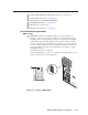
Table Of Contents
- Chapter 1 • Introduction
- Chapter 2 • Installation
- Chapter 3 • Virtualization/Control Software
- Explaining Virtual I/O Switching
- Virtualization/Control Program
- Creating a virtual I/O switching system (map)
- Reassigning virtual I/O connectors
- Creating rooms within the system
- Remote controlling the Matrix 12800 system
- Programming the matrix offline (emulate mode)
- Saving and restoring matrix settings
- Creating program byte strings
- Ethernet operation
- Windows buttons and drop boxes
- Special Characters
- Chapter 4 • Programming Guide
- Chapter 5 • Web Operations
- Chapter 6 • Upgrades and Maintenance
- Opening and Closing the Matrix Switcher
- Removing and Installing the Fan Assembly
- Removing and Installing the Power Supply Module
- Replacing the Fuse
- Removing and Cleaning the Filter
- Setting the DIP Switches
- Removing and Installing the Controller Card and Replacing the Firmware
- Removing and Installing the I/O Card and Setting the Audio Gain
- Troubleshooting
- Appendix A • Ethernet Connection
- Appendix B • Reference Information
- Inside rear cover: warranty

2-3
Matrix 12800 Switchers • Installation
PRELIMINARY
Rack Mounting the Switcher
The Matrix 12800 sync, wideband video, video, and audio BMEs are rack-
mountable, 10U high, 17.5-inch wide (19-inch wide, including rack ears) metal
enclosures. The appropriate rack mounting kit is included with the switcher. Rack
mount the switcher as follows:
UL guideline
The following Underwriters Laboratories (UL) guidelines pertain to the installation
of the Matrix 12800 switcher BME into a rack.
1. Elevated operating ambient temperature — If installed in a closed or
multi-unit rack assembly, the operating ambient temperature of the rack
environment may be greater than room ambient. Therefore, consider installing
the equipment in an environment compatible with the 122 °F (+50 °C)
maximum ambient temperature (Tma) specified by Extron.
2. Reduced air flow — Installation of the equipment in a rack should be such
that the amount of air flow required for safe operation of the equipment is not
compromised.
3. Mechanical loading — Mounting of the equipment in the rack should be such
that a hazardous condition is not achieved due to uneven mechanical loading.
4. Circuit overloading — Consideration should be given to the connection of the
equipment to the supply circuit and the effect that overloading of the circuits
might have on overcurrent protection and supply wiring. Appropriate
consideration of equipment nameplate ratings should be used when
addressing this concern.
5. Reliable earthing (grounding) — Reliable earthing of rack-mounted
equipment should be maintained. Particular attention should be given to
supply connections other than direct connections to the branch circuit (e.g. use
of power strips.
Mounting intruction
1. Insert the switcher into the rack, align the holes in the mounting bracket with
those of the rack.
2. Secure the switcher to the rack using the supplied machine screws.