
User Guide User Manual

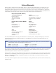

Table Of Contents
- Chapter 1 • Introduction
- Chapter 2 • Installation
- Chapter 3 • Virtualization/Control Software
- Explaining Virtual I/O Switching
- Virtualization/Control Program
- Creating a virtual I/O switching system (map)
- Reassigning virtual I/O connectors
- Creating rooms within the system
- Remote controlling the Matrix 12800 system
- Programming the matrix offline (emulate mode)
- Saving and restoring matrix settings
- Creating program byte strings
- Ethernet operation
- Windows buttons and drop boxes
- Special Characters
- Chapter 4 • Programming Guide
- Chapter 5 • Web Operations
- Chapter 6 • Upgrades and Maintenance
- Opening and Closing the Matrix Switcher
- Removing and Installing the Fan Assembly
- Removing and Installing the Power Supply Module
- Replacing the Fuse
- Removing and Cleaning the Filter
- Setting the DIP Switches
- Removing and Installing the Controller Card and Replacing the Firmware
- Removing and Installing the I/O Card and Setting the Audio Gain
- Troubleshooting
- Appendix A • Ethernet Connection
- Appendix B • Reference Information
- Inside rear cover: warranty

Matrix 12800 Switchers • Reference Information
B-2
Reference Inforation
PRELIMINARY
Specication
Video— wideband/video BME
Routing ........................................... 32 x 16 or larger matrix up to 128 x 128, depending on the configuration
Gain ................................................. Unity
Bandwidth
Wideband models ............. 375 MHz (-3 dB), fully loaded
0 - 10 MHz .................. No more than +0.1 dB to -0.1 dB
0 - 130 MHz ................ No more than +4 dB to -.25 dB
Video models ..................... 150 MHz (-3 dB), fully loaded
0 - 10 MHz .................. No more than +0.1 dB to -0.1 dB
0 - 130 MHz ................ No more than +0.5 dB to -0.5 dB
Phase between I/Os ...................... <1.28° at 3.58 MHz
Differential phase error ................ 0.1%, 3.58 to 4.43 MHz
Differential gain error ................... 0.1°, 3.58 to 4.43 MHz
Max. propagation of delay ........... 5 ns typical (±1 ns)
Crosstalk ......................................... -80 dB @ 1 MHz, -62 dB @ 10 MHz, -52 dB @ 30 MHz
Switching speed ............................ 200 ns (max.)
Video input— wideband/video BME
Number/signal type
Wideband models ............. Up to 128 (varies with configuration) RGBHV, RGBS, RGsB, RsGsBs,
component video, S-video, composite video
Video models ..................... Up to 128 (usable quantity varies with configuration) component video,
S-video, composite video
Connectors ..................................... 128 female BNC (usable quantity varies with model)
Nominal levels ............................... 1 Vp-p for Y of component video and S-video, and for composite video
0.7 Vp-p for RGB and for R-Y and B-Y of component video
0.3 Vp-p for C of S-video
Minimum/maximum levels ........ Analog: 0.5 V to 1.5 Vp-p with no offset
Impedance ...................................... 75 ohms
Return loss ...................................... <-30 dB @ 5 MHz
Video output— wideband/video BME
Number/signal type ..................... Up to 128 (varies with configuration) RGBHV, RGBS, RGsB, RsGsBs,
component video, S-video, composite video
Connectors ..................................... 128 female BNC (usable quantity varies with model)
Nominal levels ............................... 1 Vp-p for Y of component video and S-video, and for composite video
0.7 Vp-p for RGB and for R-Y and B-Y of component video
0.3 Vp-p for C of S-video
Maximum level .............................. 2 Vp-p
Impedance ...................................... 75 ohms
Return loss ...................................... -25 dB to input section @ up to 50 MHz
DC offset ......................................... ±10 mV typical with input at 0 offset
Switching type ............................... Triple-Action
™
Slew rate ......................................... >200 V/ms
Snc— nc BME
Input and output types ................ Software configurable for RGBHV or RGBS
Sync connectors ............................. Up to 128 female BNC (usable quantity varies with configuration)
Input level ...................................... 0.5 V to 5 Vp-p (4 Vp-p nominal)
Output level ................................... 5 Vp-p
Gain ................................................. AGC to TTL: 4.0 V to 5.0 Vp-p