
User Guide User Manual
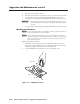
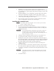
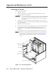
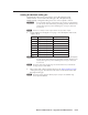
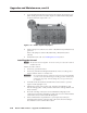
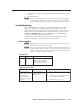
Table Of Contents
- Chapter 1 • Introduction
- Chapter 2 • Installation
- Chapter 3 • Virtualization/Control Software
- Explaining Virtual I/O Switching
- Virtualization/Control Program
- Creating a virtual I/O switching system (map)
- Reassigning virtual I/O connectors
- Creating rooms within the system
- Remote controlling the Matrix 12800 system
- Programming the matrix offline (emulate mode)
- Saving and restoring matrix settings
- Creating program byte strings
- Ethernet operation
- Windows buttons and drop boxes
- Special Characters
- Chapter 4 • Programming Guide
- Chapter 5 • Web Operations
- Chapter 6 • Upgrades and Maintenance
- Opening and Closing the Matrix Switcher
- Removing and Installing the Fan Assembly
- Removing and Installing the Power Supply Module
- Replacing the Fuse
- Removing and Cleaning the Filter
- Setting the DIP Switches
- Removing and Installing the Controller Card and Replacing the Firmware
- Removing and Installing the I/O Card and Setting the Audio Gain
- Troubleshooting
- Appendix A • Ethernet Connection
- Appendix B • Reference Information
- Inside rear cover: warranty
6-19
Matrix 12800 Switchers • Upgrades and Maintenance
PRELIMINARY
Setting the default audio gain
By default, the audio gain of each output is set to 0 dB (unbalanced) and
6 dB (balanced). You can reduce this setting by 6 dB (-6 dB [unbalanced],
0 dB [balanced]). Change the audio gain for one or more outputs as follows:
C
Do not touch the electronic components or the connectors on the backplane
or on the circuit cards without being electrically grounded. Handle circuit
cards by their edges only. ESD can damage ICs, even if you cannot feel,
see, or hear it.
N
Remove two cards for a stereo output and one card of a mono output.
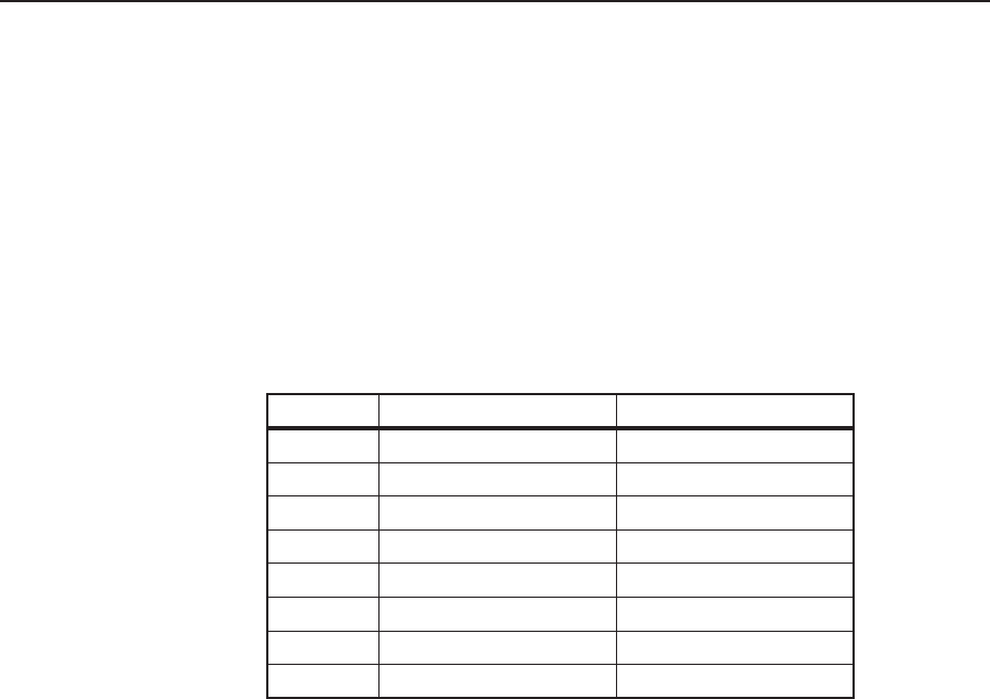
1. Use the table below and figure 6-15 on page 6-17 to identify the cards for the
output to be set.
O
utput
O
utput cards (stereo)
O
utput card (mono)
1
- 16
L
eft 1, Right 1
L
eft 1
1
6 - 32
L
eft 2, Right 2
L
eft 2
3
3 - 48
L
eft 3, Right 3
L
ef 3t
4
9 - 64
L
eft 4, Right 4
L
eft 4
6
5- 80
L
eft 5, Right 5
L
eft 5
8
1 - 96
L
eft 6, Right 6
L
eft 6
9
7 - 112
L
eft 7, Right 7
L
eft 7
1
13 - 128
L
eft 8, Right 8
L
eft 8
C
Do not touch the electronic components or the connectors on the backplane
or on the circuit cards without being electrically grounded. Handle circuit
cards by their edges only. ESD can damage ICs, even if you cannot feel,
see, or hear it.
N
The audio output cards are the longer cards in the bottom row, inside the I/O
cardcage door of an audio BME.
2. Remove the audio output cards from the card. See “Removing the I/O card“,
on the previous page. Place the removed card on an anti-static surface with
the jumpers facing up.
N
The audio cards are shipped without jumpers. Jumpers are available using
Extron part # 10-076-10.