
User Guide User Manual
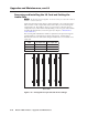
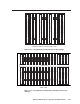
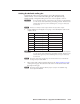
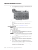
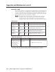
Table Of Contents
- Chapter 1 • Introduction
- Chapter 2 • Installation
- Chapter 3 • Virtualization/Control Software
- Explaining Virtual I/O Switching
- Virtualization/Control Program
- Creating a virtual I/O switching system (map)
- Reassigning virtual I/O connectors
- Creating rooms within the system
- Remote controlling the Matrix 12800 system
- Programming the matrix offline (emulate mode)
- Saving and restoring matrix settings
- Creating program byte strings
- Ethernet operation
- Windows buttons and drop boxes
- Special Characters
- Chapter 4 • Programming Guide
- Chapter 5 • Web Operations
- Chapter 6 • Upgrades and Maintenance
- Opening and Closing the Matrix Switcher
- Removing and Installing the Fan Assembly
- Removing and Installing the Power Supply Module
- Replacing the Fuse
- Removing and Cleaning the Filter
- Setting the DIP Switches
- Removing and Installing the Controller Card and Replacing the Firmware
- Removing and Installing the I/O Card and Setting the Audio Gain
- Troubleshooting
- Appendix A • Ethernet Connection
- Appendix B • Reference Information
- Inside rear cover: warranty
Upgrade and Maintenance, cont’d
Matrix 12800 Switchers • Upgrades and Maintenance
6-16
PRELIMINARY
Reoving and Intalling the I/O Card and Setting the
Audio Gain
N
The I/O cards are hot-swappable. You do not need to power down the switcher to
remove an I/O card.
Input and output circuit cards (figure 6-13 through figure 6-15) can be replaced for
fault correction. Audio output cards must be removed if you want to change the
output audio gain. Beyond those actions, you can increase or decrease the I/O
configuration (size) of the Matrix 12800 by adding or removing I/O cards and then
rerunning the Virtualization/Control Program (see chapter 3, “Virtualization/
Control software”).
The following table identifies the number of inputs that each input card supports
and the number of outputs that each output card supports. Use this table to
determine how the size of the matrix changes with the removal or installation of a
single card.
BME
Number of inputs
per input card
Number of outputs
per output card
Sync 32 64
Wideband/video 32 16
Audio 16 16
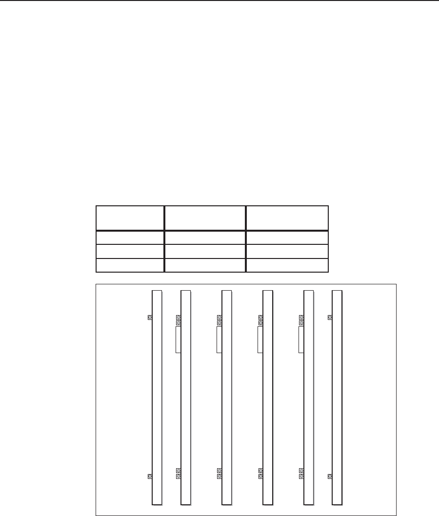
Front
Sync cards
Sync Outputs 65-128
Green
Red
Sync Inputs 97-128
Green
Red
Sync Inputs 65-96
Green
Red
Sync Inputs 33-64
Green
Red
Sync Inputs 1-32
Green
Red
Sync Outputs 1-64
Green
Red
Figure 6-13 — Arrangement of sync I/O cards in the cardcage