
User Guide User Manual
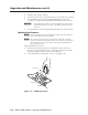
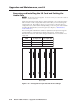
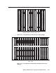
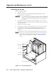
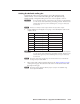
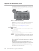
Table Of Contents
- Chapter 1 • Introduction
- Chapter 2 • Installation
- Chapter 3 • Virtualization/Control Software
- Explaining Virtual I/O Switching
- Virtualization/Control Program
- Creating a virtual I/O switching system (map)
- Reassigning virtual I/O connectors
- Creating rooms within the system
- Remote controlling the Matrix 12800 system
- Programming the matrix offline (emulate mode)
- Saving and restoring matrix settings
- Creating program byte strings
- Ethernet operation
- Windows buttons and drop boxes
- Special Characters
- Chapter 4 • Programming Guide
- Chapter 5 • Web Operations
- Chapter 6 • Upgrades and Maintenance
- Opening and Closing the Matrix Switcher
- Removing and Installing the Fan Assembly
- Removing and Installing the Power Supply Module
- Replacing the Fuse
- Removing and Cleaning the Filter
- Setting the DIP Switches
- Removing and Installing the Controller Card and Replacing the Firmware
- Removing and Installing the I/O Card and Setting the Audio Gain
- Troubleshooting
- Appendix A • Ethernet Connection
- Appendix B • Reference Information
- Inside rear cover: warranty
Upgrade and Maintenance, cont’d
Matrix 12800 Switchers • Upgrades and Maintenance
6-14
PRELIMINARY
4. Slide the card out of the cardcage.
5. Place the removed card on an anti-static surface or in an anti-static container.
6. If a replacement card is not being installed immediately, close the fan
assembly door and turn the left and right knurled knobs ¼-turn clockwise.
C
Ensure that you close and secure the fan assembly door when you have
finished this maintenance procedure. The Matrix 12800 may overheat
otherwise.
7. If a replacement card is not being installed immediately, close the front door.
Updating the rware
N
If your system has primary and redundant controller cards, both cards must
have the same firmware revisions installed.
N
The ICs that contain the firmware for the matrix switcher also contain the
memory in which presets and audio levels are saved. When you replace the IC,
these settings are lost. You may want to record the presets and audio levels
before you replace the IC.
Replace the firmware as follows:
1. If the firmware is being replaced on an installed controller card, remove
the card, see “Removing the primary or redundant controller card” in this
chapter, placing the controller card on an anti-static mat.
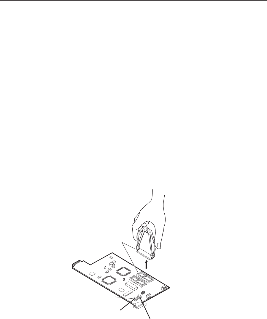
2. Locate the PROM to be replaced, IC U1, U2, or U6 (figure 6-12).
U1
U2
U6
Align notches.
Align notches.
Figure 6-12 — PROM replacement