
User Guide User Manual
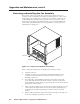
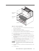
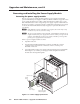
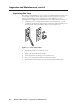
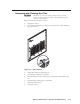
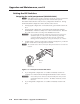
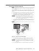
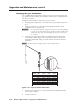
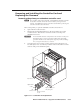
Table Of Contents
- Chapter 1 • Introduction
- Chapter 2 • Installation
- Chapter 3 • Virtualization/Control Software
- Explaining Virtual I/O Switching
- Virtualization/Control Program
- Creating a virtual I/O switching system (map)
- Reassigning virtual I/O connectors
- Creating rooms within the system
- Remote controlling the Matrix 12800 system
- Programming the matrix offline (emulate mode)
- Saving and restoring matrix settings
- Creating program byte strings
- Ethernet operation
- Windows buttons and drop boxes
- Special Characters
- Chapter 4 • Programming Guide
- Chapter 5 • Web Operations
- Chapter 6 • Upgrades and Maintenance
- Opening and Closing the Matrix Switcher
- Removing and Installing the Fan Assembly
- Removing and Installing the Power Supply Module
- Replacing the Fuse
- Removing and Cleaning the Filter
- Setting the DIP Switches
- Removing and Installing the Controller Card and Replacing the Firmware
- Removing and Installing the I/O Card and Setting the Audio Gain
- Troubleshooting
- Appendix A • Ethernet Connection
- Appendix B • Reference Information
- Inside rear cover: warranty
Upgrade and Maintenance, cont’d
Matrix 12800 Switchers • Upgrades and Maintenance
6-10
PRELIMINARY
Setting the DIP Switche
Swapping the erial port protocol (RS-232/RS-422)
N
If this BME is equipped with a redundant controller, the primary and redundant
controllers must be configured for the same communications protocol.
The Matrix 12800 controller cards are factory configured for RS-232 use. Change
the RS-232/RS-422 configuration of the controller card as follows:
1. If changing the configuration of an installed card, open and remove the front
door.
2. If changing the configuration of an installed card, turn the left and right
knurled knobs on the fan assembly door ¼-turn counterclockwise. Raise the
door and rest it on the roof of the power distribution enclosure.
C
Do not touch the electronic components or the connectors on the power
distribution plane or on the circuit cards without being electrically
grounded. Handle circuit cards by their edges only. Electrostatic
discharge (ESD) can damage ICs, even if you cannot feel, see, or hear it.
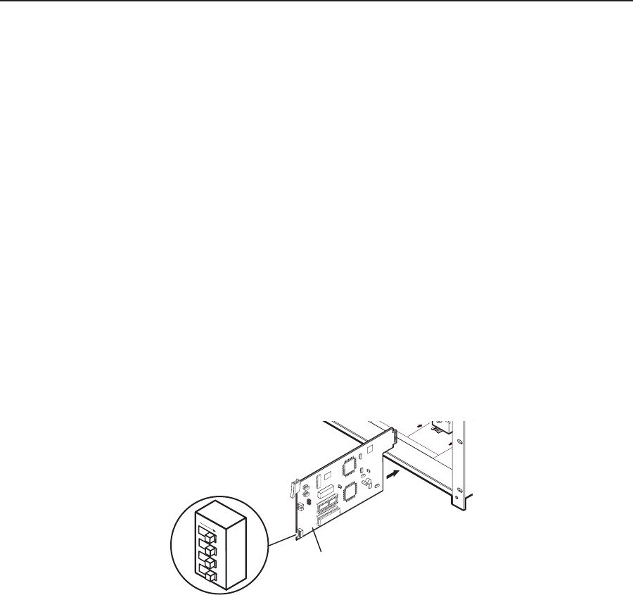
3. Set DIP switch 3, on the rear edge of the controller card (figure 6-8), to the Off
position for RS-232 or to the On position for RS-422.
N
The controller card is shown removed for clarity, but the card does not need to be
removed.
PRIMARY A
REDUND
ANT A
ON = GOOD
OFF = F
AILED
2 LED's :
ON = GOOD
OFF = FAILED
2 LED's :
PR
IMAR
Y B
REDUND
ANT B
ON = GOOD
OFF = FAILED
2 LED's :
ON = GOOD
OFF = FAILED
2 LED's :
CONT
POW E R S U P PLY B
POW E R S U P PLY A
Serial Port
Selection
DIP Switch (3)
Controller
Board
1 2
3 4
ON
Figure 6-8 — Serial port selection DIP switch
4. If you changed the configuration of a card that is installed, close the fan
assembly door and turn the left and right knurled knobs ¼-turn clockwise.
C
Ensure that you close and secure the fan assembly door when you have
finished this maintenance procedure. The Matrix 12800 may overheat
otherwise.
5. If you changed the configuration of a card that is installed, close the front
door.