
User Guide User Manual
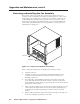
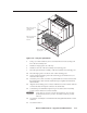
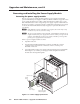
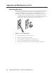
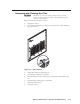
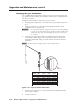
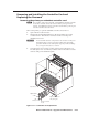
Table Of Contents
- Chapter 1 • Introduction
- Chapter 2 • Installation
- Chapter 3 • Virtualization/Control Software
- Explaining Virtual I/O Switching
- Virtualization/Control Program
- Creating a virtual I/O switching system (map)
- Reassigning virtual I/O connectors
- Creating rooms within the system
- Remote controlling the Matrix 12800 system
- Programming the matrix offline (emulate mode)
- Saving and restoring matrix settings
- Creating program byte strings
- Ethernet operation
- Windows buttons and drop boxes
- Special Characters
- Chapter 4 • Programming Guide
- Chapter 5 • Web Operations
- Chapter 6 • Upgrades and Maintenance
- Opening and Closing the Matrix Switcher
- Removing and Installing the Fan Assembly
- Removing and Installing the Power Supply Module
- Replacing the Fuse
- Removing and Cleaning the Filter
- Setting the DIP Switches
- Removing and Installing the Controller Card and Replacing the Firmware
- Removing and Installing the I/O Card and Setting the Audio Gain
- Troubleshooting
- Appendix A • Ethernet Connection
- Appendix B • Reference Information
- Inside rear cover: warranty
Upgrade and Maintenance, cont’d
Matrix 12800 Switchers • Upgrades and Maintenance
6-6
PRELIMINARY
Reoving and Intalling the Power Suppl Module
Reoving the power uppl odule
The two or four power supply modules (primary power supplies A and B and
optional redundant power supplies A and B) are identical and hot-swappable. Each
power supply module has two LEDs, visible when the fan assembly door is open,
that indicate the status of the voltages that power supply outputs. If both LEDs are
lit, the power supply is operating normally. If either LED is unlit, the power supply
is out of tolerance and should be reseated, swapped, or replaced at the earliest
opportunity.
N
If this BME does not have redundant power supplies, the switcher may or may
not shut down for an out of tolerance voltage.
N
The power supply modules are hot-swappable. If this BME has redundant power
supplies A and B, each power supply can be removed without powering down the
switcher. If the BME does not have power supply redundancy, removing either
primary power supply shuts down the matrix.
Remove a power supply module as follows:
1. Open the front door.
2. Turn the left and right knurled knobs on the fan assembly door ¼-turn
counterclockwise. Raise the door and rest it on the roof of the power
distribution enclosure.
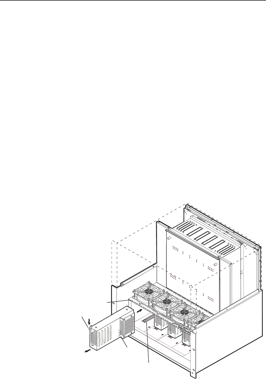
3. Grasp the handle on the power supply module and push down on the thumb
detent (figure 6-5). Pull the power supply module straight back until the
module clears the alignment guides.
PRIMAR
Y A
REDUND
ANT A
ON = GOOD
OFF = FAILED
2 LED's :
ON = GOOD
OFF = FAILED
2 LED's :
PRIMARY B
REDUND
ANT B
ON = GOOD
OFF = FAILED
2 LED's :
ON = GOOD
OFF = FAILED
2 LED's :
CONT
POW E R S U P PLY B
POW E R S U P PLY A
2 LEDs
Thumb
Detent
Align power supply
with plastic guides.
Primary A
Power Supply
Open fan door
Figure 6-5 — Power supply replacement