Matrix 12800 Series Matrix 12800 Wideband, Video, Sync, and Audio Matrix Switchers 68-556-01 Rev.
Precautions Safety Instructions • English Warning This symbol is intended to alert the user of important operating and maintenance (servicing) instructions in the literature provided with the equipment. Power sources • This equipment should be operated only from the power source indicated on the product. This equipment is intended to be used with a main power system with a grounded (neutral) conductor. The third (grounding) pin is a safety feature, do not attempt to bypass or disable it.
FCC Class A Notice This equipment has been tested and found to comply with the limits for a Class A digital device, pursuant to part 15 of the FCC Rules. Operation is subject to the following two conditions: (1) this device may not cause harmful interference, and (2) this device must accept any interference received, including interference that may cause undesired operation.
Table of Contents Chapter One • Introduction ........................................................................................................ 1-1 About the Matrix 12800 Switchers .................................................................................. 1-2 Features ............................................................................................................................................. 1-4 Definitions .......................................................................
Table of Contents, cont’d Programming the matrix offline (emulate mode) .............................................................. 3-18 Saving and restoring matrix settings .................................................................................... 3-20 Creating program byte strings ............................................................................................... 3-21 Ethernet operation ...............................................................................................
Configuration Tab ....................................................................................................................... 5-5 System Configuration page ...................................................................................................... 5-5 Administration fields ............................................................................................................ 5-6 Matrix IP settings fields ............................................................................
Table of Contents, cont’d Removing and Installing the I/O Card and Setting the Audio Gain ........... 6-16 Removing the I/O card ............................................................................................................. 6-18 Setting the default audio gain .............................................................................................. 6-19 Installing the I/O card ..............................................................................................................
1 Chapter One Introduction About the Matrix 12800 Switchers Features Definitions PRELIMINARY Matrix 12800 Switchers
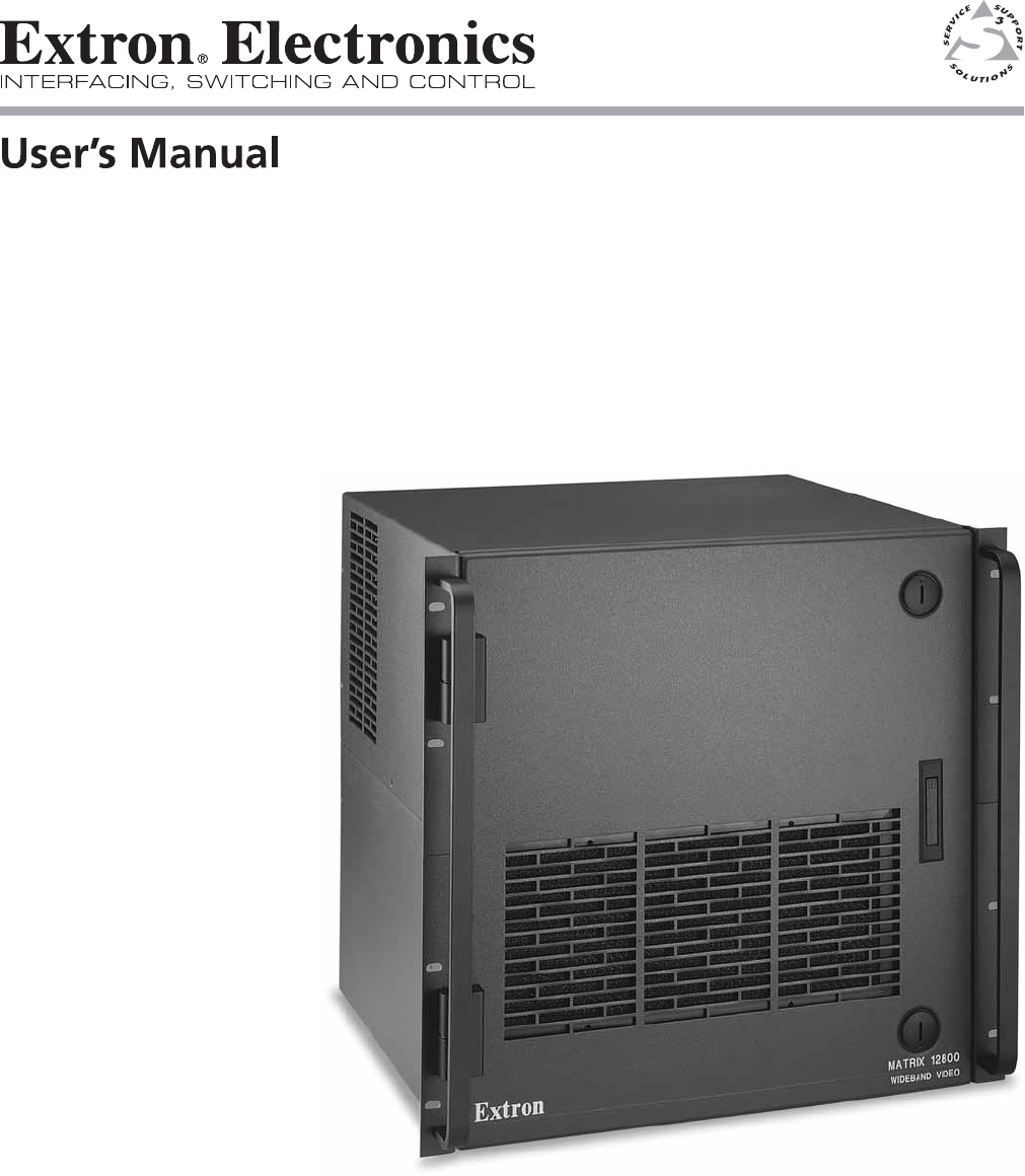
Introduction About the Matrix 12800 Switchers The Extron Matrix 12800 Series of switchers is a family of matrix switcher basic module enclosures (BMEs) and an optional front panel controller (FPC 5000) that allows you to create video and audio matrix systems with up to 128 inputs and 128 outputs specifically tailored to meet your requirements.
EXT.
Introduction, cont’d Features Input and output connectors — All connectors are clearly labeled as either input or output for easy installation. With the Extron virtualization/control software, a visual map can be printed for easy representation of the virtual I/Os. This feature reduces the time required for setup and programming. Bandwidth — Bandwidth is a minimum of 375 MHz (-3 dB), fully loaded.
The MKP 1200 is directly connected to the MCP/MKP Comm port on BME 0 of the Matrix 12800 system. The MCP 1000 master control panel is connected to one of the RS-232/RS-422 ports. MCP 1000 slave control panels, MKP 1000 slave control keypads, or both are connected to the MCP 1000 master control panel. The remote control devices are easy to use and provide tactile buttons for quick selection.
Introduction, cont’d PRELIMINARY Operational reliability — The Matrix 12800 can support round-the-clock operation in mission-critical applications, using a combination of self-diagnosis, hotswappable components, and optional redundant components. • Advanced computer-aided diagnostics — The Matrix 12800 performs self diagnostics, 24 hours a day, of the I/O cards, primary and redundant power supply voltages, controller cards, cooling status, and the overall functional status of the matrix.
• Dual redundant, hot swappable cooling fans — Four cooling fans are provided for ventilation and heat management. Fan and temperature sensors identify problems, which are reported locally with visual indications and remotely via the Ethernet and serial port links. Fans and the filter are easily replaceable through the front door with only a screwdriver required.
Introduction, cont’d Definitions The following terms apply to Extron Matrix Switchers, and are used throughout this manual: Tie — An input-to-output connection. Set of ties — An input tied to two or more outputs. (An output can never be tied to more than one input.) Configuration — May consist of one tie or one or more sets of ties. Current configuration — The configuration that is currently being used (also called configuration 0). Global memory preset — A configuration that has been stored.
2 Chapter Two Installation Installation Overview Rack Mounting the Switcher Rear Panel Connections and Settings Other Settings PRELIMINARY Matrix 12800 Switchers
Installation Installation Overview The Matrix 12800 BMEs that make up a Matrix 12800 system can be installed in a rack or a cabinet, if desired. Each BME must be connected on a daisy chain to the other BMEs in the system and cannot be separated from the other BMEs by more than 25 feet (7.6 m). The BMEs can be rack- or cabinet-mounted in any order. Give careful consideration to the location of the equipment in a room. Poor planning can result in problems.
Rack Mounting the Switcher The Matrix 12800 sync, wideband video, video, and audio BMEs are rackmountable, 10U high, 17.5-inch wide (19-inch wide, including rack ears) metal enclosures. The appropriate rack mounting kit is included with the switcher. Rack mount the switcher as follows: UL guidelines 1. Elevated operating ambient temperature — If installed in a closed or multi-unit rack assembly, the operating ambient temperature of the rack environment may be greater than room ambient.
Installation, cont’d Rear Panel Connections and Settings All connectors and switches (with the exception of the serial port protocol, baud rate, and sync termination DIP switches) are on the rear panel. Figure 2-1 shows the Matrix 12800 wideband video switcher. The sync and video switcher is housed in similar 10U enclosures. The Matrix 12800 audio switcher is housed in a similar 10U enclosure, but with 3.5 mm, 5-pole captive screw connectors.
k l m n o p Balanced and unbalanced audio input connectors — See page 2-13. Audio outputs connectors — See page 2-14. FPC Comm port — (FUTURE CAPABILITY) MCP/MKP Comm ports — See page 2-14. Ethernet port — See page 2-15. External Sync connectors — See page 2-16. Pre-virtualization operations BME settings BME address switch — Each BME must be set to a unique address of 0 through 8. Address 9 is invalid.
Installation, cont’d b BME COMM interconnect ports — If the Matrix 12800 system consists of more than one BME, the BMEs must be connected together in a daisy chain using Extron-supplied RJ-45 cables. Connect the first daisy chain from the BME Comm Out connector on BME 0 to the nearest BME Comm In connector on the BME (figure 2-3). In a rack whose BMEs are numbered sequentially, this would be BME 1. But, since not all systems are configured alike, call this module BME n.
Serial ports c Primary and Secondary RS-232/RS-422 ports — For systems consisting of a single switcher or for BME 0 on a multi-BME system, connect host devices (such as computers or touch panel control systems) or MCP 1000 remote control panels (see the MCP 1000 Remote Control Panel User Guide) to the Primary and Secondary RS-232/RS-422 ports (figure 2-4). These 9-pin D connectors provide for serial RS-232/RS-422 control of the matrix switcher. Figure 2-5 shows how to wire the connectors.
Installation, cont’d Ground d Ground terminal — If the power outlets do not provide connections to the protective ground of the building, connect ground straps between this terminal lug on all BMEs and a hard building ground. Secure the ground straps with the nut and washer included with each BME. N You are responsible for providing the ground straps. N Some earlier BMEs do not have the ground terminal.
f Primary and Redundant AC Power Input switches — For BME 0 to recognize all of the BMEs in the daisy chain, BME 0 may not be powered on before the other BMEs. Rather, turn on BME 0 at the same time or after the other BMEs. N During shipment, circuit cards can become dislodged from their edge connectors during shipment. Reseat all I/O and controller cards before initial power up. See chapter 6, “Upgrades and Maintenance”, for the applicable procedures.
Installation, cont’d Virtualization/Control Software The Extron-supplied Matrix 12800 System Virtualization/Control software, which runs on a Windows-type computer and communicates with the matrix switcher via the Ethernet, RS-232/RS-422 ports, or each on BME 0, provides an easy way to virtualize the matrix switcher and to set up ties and sets of ties. Virtualization is required before system operation to map the virtual inputs and outputs to the physical inputs and outputs.
4. Follow the on-screen instructions. By default, the installation of the Matrix Switchers Control Program creates a MTRX6400 directory, and it places the following two icons into a group folder named “Extron Electronics\Matrix Switchers”: • Matrix Switcher 6400+12800 Control Program • Matrix 12800 Help Starting the software Click Start > Programs > Extron Electronics > Matrix 6400+12800 Control Program to start the program. Select the appropriate Comm port or Ethernet port, or select Emulate mode.
Installation, cont’d Post-Virtualization operations Wideband video, low resolution video, and sync connections (wideband, video, and sync BMEs only) 9 10 Wideband and sync input and output connectors — Use worksheets, printouts from the Matrix 12800 System/Virtualization Control program, or both to determine the virtual connection on each physical input and output connection. Connect video and sync inputs and outputs to these BNC connectors.
N For audio inputs and outputs, the length of exposed wires is critical. The ideal length is 3/16-inch (5 mm). k • If the stripped section of wire is longer than 3/16-inch, the exposed wires may touch, causing a short circuit between them. • If the stripped section of wire is shorter than 3/16-inch, wires can be easily pulled out even if tightly fastened by the captive screws. Balanced and unbalanced audio input connectors — Each input has a 3.
Installation, cont’d l Audio outputs connectors — These 3.5 mm, 5-pole captive screw connectors output the selected unamplified, line level audio. Connect audio devices, such as an audio amplifier or powered speakers. See figure 2-12 to properly wire an output connector. Use the supplied tiewrap to strap the audio cable to the extended tail of the connector.
o Ethernet port — For systems consisting of a single switcher or for BME 0 on a multi-BME system, if desired connect the Matrix 12800 either directly to an FPC 5000 Front Panel Controller or to an Ethernet LAN via this RJ-45 connector (figure 2-14). If you are connecting to a LAN, you can still use an FPC 5000 as one of the other nodes of the LAN.
Installation, cont’d Crossover Cable Pins: 12345678 End 1 Wire color Pin Insert Twisted Pair Wires Pin End 1 Wire color End 2 Wire color 1 White-green White-orange 1 White-orange White-orange 2 Green Orange 2 Orange Orange 3 White-orange White-green 3 White-green White-green 4 Blue Blue 4 Blue Blue 5 White-blue White-blue 5 White-blue White-blue 6 Orange Green 6 Green 7 White-brown White-brown 7 White-brown White-brown 8 Brown Brown 8 Brown Brown T568A RJ-45 Connect
Figure 2-17 shows another configuration, in which the timing source passes through three video cameras and a video scan converter before connecting to the switcher. This type of video camera is capable of synchronizing with the external timing source for video editing applications.
Installation, cont’d Other Settings Serial port protocol switches The controller card has a DIP switch that allows you to select between the RS-232 and RS-422 protocol for the rear panel RS-232/RS-422 ports. RS-232 is the default setting. See “Swapping the serial port protocol (RS-232/RS-422)” in chapter 6, “Upgrades and Maintenance”, to select a different serial port protocol.
3 Chapter Three Virtualization/Control Software Explaining Virtual I/O Switching Virtualization/Control Program Special Characters PRELIMINARY Matrix 12800 Switchers
Virtualization/Control Software Explaining Virtual I/O Switching A Matrix 12800 system consists of from one to nine BMEs, each of which can have as many as 128 inputs and 128 outputs. It is usually desirable to have certain inputs switch together as a set, to follow each other. For example, if the system consists of a 128 x 128 video BME and a 128 x 128 audio BME, you want your video images on your video monitors to match the audio from the sound system (for example, video and audio from a DVD).
The largest possible system consists of three 128 x 128 video BMEs, two 128 x 128 sync BMEs, and one 128 x 128 audio BME. This system can then be mapped to become a matrix with 128 virtual inputs and 128 virtual outputs in seven virtual planes (R, G, B, H, V, left-channel audio, and right-channel audio). All of these configurations are established by creating a virtual map with the Virtualization/Control software and downloading the virtual map to the BME.
Virtualization/Control Software, cont’d Virtualization/Control Program The Extron-supplied Matrix 12800/6400/3200 Virtualization/Control software runs in a Windows-type computer and communicates with the matrix switcher via the primary or secondary RS-232/RS-422 ports or the Ethernet port on BME 0. The software provides an easy way for you to virtualize the matrix switcher and to establish rooming presets.
Creating a virtual I/O switching system (map) The following detailed example uses the Virtualization/Control software to create a virtual I/O switching system within the physical hardware. This process generates and uploads a virtual map to the Matrix 12800 hardware. The physical Matrix 12800 system consists of from one to nine BMEs, each of which can have as many as 128 inputs and 128 outputs in 1 to 7 virtual planes.
Virtualization/Control Software, cont’d PRELIMINARY After you select the Comm port and click OK, the software looks for the Matrix system and reads its hardware configuration, the type and size of each BME. The software then reads all of the current settings, such as the ties, presets, and virtual map, and displays a graphical representation of the ties in the program window (figure 3-2).
On the menu bar, click System-Config to show the Virtual Map screen (figure 3-3). PRELIMINARY 4.
Virtualization/Control Software, cont’d 5. On the menu bar, click Configure > Physical Switchers to show the Physical Configuration screen (figure 3-4). Check this screen to ensure that all BMEs were seen on program startup and that their type and size is reported correctly. PRELIMINARY Click the Close button to return to the Virtual Map screen. Figure 3-4 — Physical Configuration screen 6. On the menu bar, click Configure > Virtual Switcher-Basic to show the Virtual Configuration screen (figure 3-5).
a. If a sync BME was found, you can specify, in the Sync Config box, whether the Virtualization/Control program is to map the system using Composite sync (one plane) or Separate H + V sync (two planes). b. In the Ordering box, you can specify whether the program is to organize the map assignments in a repeating pattern or grouped by plane.
Virtualization/Control Software, cont’d 10. If desired, on the Virtual Map screen menu bar, click Print Maps to create a hard copy map of the virtual system. If you send the map to a color printer (select the printer by clicking on File > Select printer on the main screen), the map prints with the red plane mapped in red, the green plane in green, the blue plane in blue, the horizontal plane in black, the vertical plane in yellow, and the audio plane in olive.
Map an unused connector to replace a current connector on the Virtual Map screen as follow: 1. Click the Edit Mode box to enable mapping. 2. Click and begin dragging the unused connector. When you start dragging the connector, the Virtual I/O Map field moves down the screen to the entry for the connector in the list field (figure 3-7). Figure 3-7 — Dragging and dropping a connector 3. Drop the connector into the Virtual Ins or Outs Map field in the appropriate frame.
Virtualization/Control Software, cont’d 4. When you are finished editing the virtual map, click the Take button to accept the changes. If you decide that you do not want these changes, click Return to Main without Taking to reject the changes. 5. Click the End Edit button to exit the edit mode. You can also drag and drop a connector to the trash can in the Virtual Map screen to delete it from the map.
3. On the menu bar, click System-Config to show the Virtual Map screen (figure 3-3). 4. On the menu bar, click Configure > Room Configuration to show the Room Mapper screen (figure 3-9). Figure 3-9 — Room Mapper screen 5. Assign virtual outputs to rooms by dragging and dropping the output circles from the Virtual Switcher Out field to the list on the right of the screen.
Virtualization/Control Software, cont’d Remote controlling the Matrix 12800 system BME 0 saves the settings in non-volatile memory, so once the system is virtualized, there is no requirement to ever run the Virtualization/Control program again. However, the Matrix 12800 can be remotely operated from a PC, running the Virtualization/Control software, connected to either of the RS-232/RS-422 ports or the Ethernet port on BME 0. Use the Virtualization/Control software to control the matrix as follows: 1.
Ties Ties appear as solid lines in various colors on main screen of the Virtualization/Control program. The different colors indicate different follow and breakaway configurations. If both video and audio are tied, the tie is indicated in blue. If video only is tied, the tie is indicated in magenta. An audio-only tie is indicated in brown. To create a tie, drag and drop from an input box to an output box. Observe that the tentative tie is indicated on the screen by a dashed line.
Virtualization/Control Software, cont’d Presets After you have created all of the ties that are needed for a specific task, the configuration can be saved as either a global or room preset. The Matrix 12800 can support up to 64 global presets and up to 10 room presets in each of up to 32 rooms. To create room presets, you must have already created rooms and assigned outputs to the rooms, see “Creating rooms within the system” earlier in this chapter. PRELIMINARY Save a preset 1.
Icons and captions For your convenience, you can assign a device icon, a name, or both to any of the virtual inputs or outputs using the devices palette. The icons are saved by the program, not sent to the switcher. Figure 3-11 — Devices screen To assign a descriptive icon to an input or output, drag and drop the desired icon from the palette to the target I/O box on the main screen. To change the icon, drag and drop the new icon.
Virtualization/Control Software, cont’d Programming the matrix offline (emulate mode) The Virtualization/Control program provides an emulation mode, in which you can build and save a configuration file off-line, without connection to a Matrix 12800 system. This file can be programmed into a switcher via the RS-232/ RS-422 port using the Matrix 12800/6400/3200 Virtualization/Control program.
5. If you have not virtualized the system represented by your startup file, the Virtual Configuration screen appears (figure 3-5). This screen shows how the software has mapped the physical system into a virtual system. There are several variables that you can change on this screen that affect the number of virtual planes and inputs and outputs that are available and how they are presented. See step 5 in “Creating a virtual I/O switching system (map)”.
Virtualization/Control Software, cont’d Saving and restoring matrix settings In on-line (as opposed to emulation mode) operation, the Virtualization/Control program reads the source file, Mtrx12800.ini, upon startup. The program reads the file to display the icons, because these items do not cause any changes in the system configuration (programming) and provide convenience to the user. Mtrx12800.ini contains all of the information needed to fully restore (program) the settings of the Matrix 12800 system.
Creating program byte strings The Matrix 12800 system can be controlled and programmed from a control system, via the RS-232/RS-422 port. The control systems need to be taught what bytes to send to the system to communicate with the Matrix system. Chapter 4 of this manual, “Programming Guide”, details the Extron Simple Instruction Set (SIS) and how to build these byte strings using a pencil and paper. The Virtualization/ Control program makes this job much easier by building the strings for you.
Virtualization/Control Software, cont’d Logging on to the switcher via the Ethernet 1. On the PC, click Start > Programs > Extron Electronics > Matrix 12800/6400/3200 Control Program to start the program. 2. When prompted for a port, select IP [LAN] (figure 3-14) and click OK. PRELIMINARY Figure 3-14 — Ethernet mode selection 3. The IP connection window appears (figure 3-15). Figure 3-15 — Address and password entry a. Examine the Matrix IP Address field in the IP Connection window.
Ethernet protocol settings The IP settings/options screen (figure 3-16) provides a location for observing and, if connected via the RS-232/RS-422 link or if logged on via the Ethernet port as an administrator, editing settings unique to the Ethernet interface. Access this screen by clicking Tools > IP Options. See appendix A, “Ethernet Connection”, for basic information about IP addresses. None of the fields on this screen can be edited while logged on as a user.
Virtualization/Control Software, cont’d Address and Name fields The Matrix IP Address field contains the IP address of the connected matrix switcher. This value is encoded in the flash memory in the switcher. The Gateway IP Address field identifies the address of the gateway to the controlling PC to be used if the matrix switcher and the mail server are not on the same subnet.
Date and Time (GMT) fields The Date field displays the current date in the Greenwich Mean Time (GMT) zone. The Time (GMT) field displays the current time in the GMT zone. If desired, adjust either of these values as follows: Click in the desired field. The field changes to an editable field appropriate to the value being change and the graphic cursor becomes a text cursor. • The Date field becomes a set date field, with the date in the format (M)M/(D)D/YYYY. Leading zeroes are not shown.
Virtualization/Control Software, cont’d Edit any of these password fields as follows: 1. Click in the desired Password field. The pointer tool becomes a text cursor. 2. Edit the case-sensitive password as desired. 3. Press the Tab key on the keyboard or click in another field to exit the Password field. 4. Click the Take button to make the password change take effect.
Windows buttons and drop boxes The buttons and drop boxes on the right side of the program window perform the following functions: RGB Mute — Toggles the video mute on and off. Audio Mute — Toggles the audio mute on and off. Room menu — Displays a list of up to 32 rooms. You can select a room from the list to display it in the window. N A Room is a subset of outputs that are logically related to each other, as determined by the operator.
Virtualization/Control Software, cont’d Tools menu Edit/View Config — Displays the Virtual Map screen, which graphically presents the virtual map and allows you to make changes to the map. PRELIMINARY List Remote Keypads — Shows the status of all possible MKP 1200 Remote Keypads. Information displayed includes: address, mode, parameter, model and firmware version (figure 3-18). To configure a keypad, select it, click the Reconfigure Keypad button.
Preferences menu Immediate Changes — Causes changes to take effect immediately. Hold/Verify Changes — Delays implementation of changes until the Changes – Take button is pressed. Show all tie-lines — Causes the main screen to display all ties at once, as shown in figure 3-2. Show 1 input’s tie-lines — Because the Show all tie-lines selection can be confusing, this selection removes all of the tie lines from the main screen.
Virtualization/Control Software, cont’d PRELIMINARY Ties as Crosspoints — Displays ties as a matrix of inputs and outputs (figure 3-20). Made ties are indicated as blue (video and audio) boxes or boxes of the applicable color for each video plane. Ties that will take effect when you click on the Take button are indicated by +. Ties that will be broken when you click on the Take button are indicated by –.
Special Characters Certain characters are reserved for specific functions. The switcher does not accept these characters as part of preset names, the name of the switcher, passwords, or locally created file names. The switcher rejects or Extron does not recommend the following characters: PRELIMINARY {space} ~ @ = ‘ [ ] { } < > ’ “ semicolon (;) colon (:) | \ and ?.
PRELIMINARY Virtualization/Control Software, cont’d 3-32 Matrix 12800 Switchers • Virtualization/Control Software
4 Chapter Four Programming Guide RS-232/RS-422 Ports Ethernet (LAN) Port Host-to-Switcher Instructions Switcher-Initiated Messages Switcher Error Responses Using the Command and Response Tables Special Characters PRELIMINARY Matrix 12800 Switchers
Programming Guide RS-232/RS-422 Ports The rear panel RS-232/RS-422 connectors (figure 4-1) of the matrix switcher BME 0 can be connected to the serial port output of a host device such as a computer running the HyperTerminal utility or a control system. This connection makes Simple Instruction Set (SIS) control of the switcher possible from the computer or host via the RS-232/RS-422 link.
Ethernet (LAN) Port The rear panel Ethernet connector (figure 4-2) on the matrix switcher BME 0 can be connected to the an Ethernet LAN or WAN. Communication between the switcher and the controlling device is via Telnet (a TCP socket using port 23). This connection makes SIS control of the switcher possible using a computer connected to the same LAN or WAN.
Programming Guide, cont’d Establishing a connection Establish a network connection to BME 0 as follows: 1. Open a TCP socket to port 23 using the IP address of the BME. N If the local system administrators have not changed the value, the factoryspecified default, 192.168.254.254, is the correct value for this field. The BME responds with a copyright message including the date, the name of the product, firmware version, part number, and the current date and time.
Switcher-Initiated Messages When a local event such as a power-up occurs, the switcher responds by sending a message to the host. The switcher-initiated messages are listed below (underlined). ](C) Copyright 2003, Extron Electronics Matrix12800, Vx.xx,date and time] The BME initiates the copyright message when it is first powered on or when connection via Internet protocol (IP) is established. “Vx.xx“ is the firmware version number.
Programming Guide, cont’d Using the Command and Response Tables The command and response tables begin on page 4-8. Lower case letters are acceptable in the command field except where indicated for the gain and attenuation commands. The table below shows the hexadecimal equivalent of each ASCII character used in the command and response table. Space ASCII to Hex Conversion Table PRELIMINARY • Symbols are used throughout the table to represent variables in the command and response fields.
= Signal type: Unassigned No audio Stereo Left mono RGB 01 11 21 RGBS 02 12 22 RGBHV 03 13 23 Composite video 04 14 24 Unassigned 00 S-video 05 15 25 Component video 06 16 26 17 27 Audio only X2) = Virtual input or output nxyyy, where n = BME number x = input or output yyy = BNC connector Example: 4i003 (BME 4, input connector 003) X2! X2@ X2# = Input size X2$ X2% X2^ X2& The number of physical inputs = Output size The number of physical outputs = BME type
Programming Guide, cont’d Command and response table for SIS commands Command ASCII command (host to switcher) Response (switcher to host) Additional description Create ties • Commands can be entered back-to-back in a string, with no spaces. For example: 1*1!02*2&02*04%4*6$. • The quick multiple tie and tie input to all output commands activate all I/O switches simultaneously. • The matrix switchers support 1-, 2-, and 3-digit numeric entries (1*1, 02*02, or 003*003).
Command and response table for SIS commands (continued) Command ASCII command (host to switcher) Response (switcher to host) Additional description Read ties N The & view tie command for RGB and the % view tie command for video can be used interchangeably on the matrix switcher. Read video and audio X@! X!] Video and audio input X! output tie tied to output X@. Read RGB output tie X@& X!] RGBHV input X! tied to output X@. Read video output tie X@% X!] Video input X! tied to output X@.
Programming Guide, cont’d Command and response table for SIS commands (continued) Command ASCII command (host to switcher) Response (switcher to host) Additional description Create and recall presets • If you try to recall a preset that is not saved, the matrix switcher responds with the error code E11. N • If you try to save a preset for a room that has not been created, the matrix switcher responds with the error code E21. • Outputs must be assigned to a room before a room preset can be created.
Command and response table for SIS commands (continued) Command ASCII command (host to switcher) Response (switcher to host) Additional description View ties, gain, mutes, presets, file status, DSVP, and input status EX1)MR} E3MR} X1!,X@1,X@2, ... X@n] Save current ties as a room preset Example: X1)*X1@, RmmX1)•SprX1@] 3*9, Rmm03•Spr09] Directly write a room preset E+X1)*X1@PX!*X@!...X!*X@$ Recall a room preset X1)*X1@. RmmX1)•SprX1@] 5*8.
Programming Guide, cont’d Command and response table for SIS commands (continued) Command ASCII command (host to switcher) Response Additional description (switcher to host) View ties, gain, mutes, presets, file status, DSVP, and input status EX(*X@*1VC} View 16 video ties for global preset X( (All inputs and outputs shown are virtual.) X!n•X!n+1•X!n+2• ... •X!n+15•Vid] Show the virtual video input tied to 16 sequential virtual outputs of preset X(, starting from output X@.
Command and response table for SIS commands (continued) Command ASCII command (host to switcher) Response (switcher to host) Additional description View ties, gain, mutes, presets, file status, DSVP, and input status View 16 audio ties for room X*, preset X1@ (All inputs and outputs shown are virtual.) EX1)*X1@*X@*2VC} X!n•X!n+1•X!n+2• ... •X!n+15•Aud] Show the virtual audio input tied to 16 sequential virtual outputs of room X*, preset X1@, starting from output X@. X1@, starting from output X@.
Programming Guide, cont’d Command and response table for SIS commands (continued) Command ASCII command Response EX@*X1*D} E4*7D} OutX@•DlyX1*] EX@D} E5D} X1*] 05] (host to switcher) (switcher to host) Additional description RGB delay Set RGB delay Example: Read RGB delay Example: Out004•Dly07] Set the RGB interval for ties to output 4 to 3.5 seconds (7 x 0.5). Output 5 switching interval is 2.5 seconds (5 x 0.5). Names • Do not use leading spaces in preset names.
Command and response table for SIS commands (continued) Command ASCII command Response (switcher to host) Additional description EX!*X@ZM} EZG} ZpmX!*X@] Intialize the virtual map size. Zpg] Clear all global presets and their names. EX(ZG} ZpgX(] Clear preset X( and its name. EZR} EX1)ZR} EZP} Zpr] Clear all rooms. ZprX1)] Clear room X1). Clear all room presets and their names.
Programming Guide, cont’d Command and response table for SIS commands (continued) Command ASCII command Response I X2!XX2@•TX2#•UX2$•MX2%XX2^] (host to switcher) (switcher to host) Additional description Information requests Information request, system Example: Information request, specific BME Input size X output size, BME type connected, number of BMEs, input map and output map.
Command and response table for IP SIS commands Symbol definitions X4) = Matrix name (Up to 240 characters) The following characters are invalid or not recommended in the name: {space} ~ , @ = ` [ ] { } < > ‘ “ ; : \ | and ?.
Programming Guide, cont’d Command and response table for IP SIS commands Command Response EX4)CN} ECN} E•CN} Ipn•X4)] EX4@CT} ECT} EX4$CI} ECI} ECH} ECC} EX4$CS} ECS} EX4$CG} ECG} EX4&CA} ECA} IptX4@] E•CA} Ipa•X4&] (host to switcher) Set matrix name (location) Read matrix name (location) Reset matrix name to factory default Set GMT time and date Read GMT time and date Set IP address Read IP address Read hardware address Read # of open connections Set subnet mask Read subnet mask Set gateway IP add
5 Chapter Five Web Operations Download the Startup Page Status Tab Configuration Tab File Management Tab Control Tab PRELIMINARY Matrix 12800 Switchers
Web Operations The Matrix 12800 can be controlled and operated through the Ethernet port on BME 0, across the LAN or WAN, using a Web browser, such as the Microsoft Internet Explorer. The browser down loads a series of displays that have the appearance of Web pages. This chapter describes the factory-installed HTML pages, which are always available and cannot be erased or overwritten. N If your Ethernet connection to the matrix switcher is unstable, try turning off the proxy server in your Web browser.
7. The switcher checks several possibilities, in the following order, and then responds accordingly: a. Does the address include a specific file name, such as 10.13.156.10/file_ name.html? If so, the switcher downloads that HTML page. b. Is there a file in the memory of the switcher that is named “index.html”? If so, the switcher downloads “index.html” as the default startup page. c.
Web Operations, cont’d BME Status page To observe more status details for a specific BME, from the System Status page, click the BME number, either at the top of the status column or in the brackets to the left of the screen. The Matrix 12800 downloads the BME Status page (figure 5-3), which provides additional information for that BME, including the size of the matrix and the number of and status of individual input cards and output cards.
DSVP page To observe the Digital Sync Validation Processing (DSVP) for an input, from the System Status page, click the DSVP link to the left of the screen (figure 5-5). N DSVP is only available in systems that include a sync BME. Select System Status Figure 5-5 — DSVP page Configuration Tab System Configuration page The Matrix 12800 downloads the System Configuration page (figure 5-6) when you click the Configuration tab.
Web Operations, cont’d Administration fields • Ethernet connection to the Matrix switcher, either entering SIS commands (see chapter 4, “Programming Guide”), using the Matrix 12800/6400/3200 Control Program (see chapter 3, “Virtualization/Control Software”), or using HTML pages, is password protected. • Connection via the RS-232/RS-422 port is not password protected. On password-protected connections, there are two levels of protection: administrator and user.
Email Settings page The Email Settings page (figure 5-7) can be reached by clicking on the Email Settings link on the system configuration page. The Email Settings page has fields for entering all of the information needed to set up the e-mail notification capabilities of the switcher. After editing any of the settings on this page, click the Submit button. PRELIMINARY Select System Configuration. Refresh.
Web Operations, cont’d Email Address fields The nine Email Address fields identify the e-mail addresses of the personnel to whom the Matrix 12800 e-mails notification of its failure and repair status. Standard e-mail address conventions (nnnnn@xxx.com) apply. The check boxes and drop box associated with each address field permit the operator to specify specific e-mail requirements for each recipient.
Control Tab Set and View Ties page You can create ties on the Set and View Ties page (figure 5-9). Access the Set and View Ties page by clicking the Control tab.
Web Operations, cont’d Create a tie as follows: 1. Click the Video Only, Audio Only, or Video & Audio button to select video, audio, or both for switching (audio follow or audio breakaway). Each mouse click of a button toggles the other two buttons off. 2. Move the mouse pointer over the matrix of input and output selection buttons. Click a button to create a preliminary tie (if not tied) or preliminary untie (if tied) of the input and output associated with that button.
Changing the input gain and attenuation (systems with audio BMEs) Users can set the level of audio gain or attenuation (-24 dB to +9 dB) for each input from the RGBHV Settings page. Audio levels can be adjusted so there are no noticeable volume differences between sources. Change the audio level setting of an input as follows: 1. Click the Input drop box. A drop-down scroll box appears (figure 5-11). 2.
Web Operations, cont’d Muting and unmuting one or all outputs Mute one or all outputs as follows: 1. To select an individual output to mute or unmute, click the Output drop box. A drop-down scroll box appears (figure 5-13). PRELIMINARY Figure 5-13 — Output selection drop box 2. Click and drag the slider or click the scroll up ( ) button or scroll down ( ) button until the desired output is visible. 3. Click the desired output. 4.
4. Click the RGB delay drop box. A drop-down scroll box appears (figure 5-15). Figure 5-15 — RGB delay drop box 5. Click the desired RGB delay. You can save and recall global presets from the Global Presets page (figure 5-16). Access the Global Presets page by clicking the Global Presets link on the left of the Set and View Ties page.
Web Operations, cont’d Saving a preset Save the current configuration (configuration 0) as a preset as follows: 1. Click the Save Preset button. 2. Select the desired preset by clicking on one of the presets listed. To create a new preset, click the on one of the [unassigned] buttons. Overwrite an existing preset by clicking on an already existing preset. 3. If desired, type over the current name in the box adjacent to the Save Preset button.
6 Chapter 6 Upgrades and Maintenance Opening and Closing the Matrix Switcher Removing and Installing the Fan Assembly Removing and Installing the Power Supply Module Replacing the Fuse Removing and Cleaning the Filter Setting the DIP Switches Removing and Installing the Controller Card and Replacing the Firmware Removing and Installing the I/O Card and Setting the Audio Gain Troubleshooting PRELIMINARY Matrix 12800 Switchers
Upgrades and Maintenance N For proper cooling and air flow, all access doors should be closed during normal switcher operations. Opening and Closing the Matrix Switcher Opening the switcher PRELIMINARY All maintenance and upgrade procedures require access to the interior of the switcher by opening the front door (figure 6-1). Gain access to the interior as follows: Door Fastener MA TR IX 12 80 0 Figure 6-1 — Opening the Matrix 12800 switcher. 6-2 1. Turn the top door fastener clockwise from 2.
Closing the switcher 1. If the door was removed, replace the door by lifting it above the hinge pins and lowering it onto the pins. 2. Shut the door. 3. Turn the bottom door fastener clockwise from 4. Turn the top door fastener counterclockwise from . to (figure 6-2).
Upgrades and Maintenance, cont’d Removing and Installing the Fan Assembly PRELIMINARY The four fans on the fan assembly door are paired; two primary fans in one assembly and two redundant fans in another assembly (figure 6-3). The two fans in the primary fan assembly share a common power connector and the two fans in the redundant fan assembly share a separate connector. The power cord for the primary fan assembly is sheathed in red, the power cord for the redundant fan assembly is sheathed in black.
Remove four nuts w/ captive washers (each fan). Remove screws from cable hold down brackets. D : O D 's O LE I D E G A L = F 2 N = O F F O IM P O ARY A W ER S U RED PP U LY NDA NT A A D : O D 's O LE I D E G A L = F 2 N = O F F O PR IM A PO W RY B ER SU PP B A D N U LY D : O D 's O LE I D E G A L = F B 2 N = T O F F N O D E R Disconnect fans at connectors. CO NT Figure 6-4 — Fan pair replacement 6.
Upgrades and Maintenance, cont’d Removing and Installing the Power Supply Module Removing the power supply module The two or four power supply modules (primary power supplies A and B and optional redundant power supplies A and B) are identical and hot-swappable. Each power supply module has two LEDs, visible when the fan assembly door is open, that indicate the status of the voltages that power supply outputs. If both LEDs are lit, the power supply is operating normally.
4. If a replacement power supply is not being installed immediately, close the fan assembly door and turn the left and right knurled knobs ¼-turn clockwise. C 5. Ensure that you close and secure the fan assembly door when you have finished this maintenance procedure. The Matrix 12800 may overheat otherwise. If a replacement power supply is not being installed immediately, close the front door. Installing the power supply module N The power supply modules are hot-swappable.
Upgrades and Maintenance, cont’d Replacing the Fuse The primary and redundant AC power circuits are independently fused. The fuses are accessible on the rear panel of the switcher. If a fuse opens, the associated primary or redundant power loop shuts down. If this BME does not have redundant power supplies, the switcher shuts down. Replace the fuse as follows: 1.
Removing and Cleaning the Filter C The filter can be removed for cleaning without powering down the switcher, but do not operate the switcher without filtering longer than necessary to clean the filter. Remove and clean the air filter as follows: Open the front door. 2. Loosen the four thumbscrews (figure 6-7) and rotate the four filter retaining clips out of the way. PRELIMINARY 1. Figure 6-7 — Filter removal 3. Lift the filter off the four retaining posts. 4.
Upgrades and Maintenance, cont’d Setting the DIP Switches Swapping the serial port protocol (RS-232/RS-422) N If this BME is equipped with a redundant controller, the primary and redundant controllers must be configured for the same communications protocol. The Matrix 12800 controller cards are factory configured for RS-232 use. Change the RS-232/RS-422 configuration of the controller card as follows: 1. If changing the configuration of an installed card, open and remove the front door. 2.
Changing the serial port baud rate N If this BME is equipped with a redundant controller, the primary and redundant controllers must be configured for the same RS-232/RS-422 communications baud rate. The Matrix 12800 controller cards are factory configured for 9600 baud rate on the RS-232/RS-422 port. Change the RS-232/RS-422 baud rate of the controller card as follows: 1. If changing the baud rate of an installed card, open and remove the front door. 2.
Upgrades and Maintenance, cont’d Changing the sync termination In a sync BME, the first eight physical inputs on each I/O card are equipped with sync termination DIP switches. Each switch provides the option of selecting either 510 ohms or 75 ohms. Change the sync termination of the sync I/O card as follows: 1. If changing the configuration of an installed card, open and remove the front door. 2. On the I/O cardcage door, turn the left and right knurled knobs ¼-turn counterclockwise. Lower the door.
Removing and Installing the Controller Card and Replacing the Firmware Removing the primary or redundant controller card N The controller cards are hot-swappable. If this BME has redundant controller cards, either controller card can be removed without powering down the switcher. If the BME does not have controller card redundancy, removing the controller card shuts down the matrix. 1. Open and remove the front door. 2.
Upgrades and Maintenance, cont’d 4. Slide the card out of the cardcage. 5. Place the removed card on an anti-static surface or in an anti-static container. 6. If a replacement card is not being installed immediately, close the fan assembly door and turn the left and right knurled knobs ¼-turn clockwise. C 7. Ensure that you close and secure the fan assembly door when you have finished this maintenance procedure. The Matrix 12800 may overheat otherwise.
3. For IC U6 — Use a PLCC IC puller to remove the existing firmware IC. Squeeze the tool to align its hooks with the slots in opposite corners of socket U6. Insert the hooks, squeeze gently, and pull the IC straight out of the socket. Set the IC aside. 4. For ICs U1 and U2 — Use your fingertips to grasp the edges of the existing firmware IC and pull the IC straight out of the socket. Set the IC aside. 5. Note the key (notch) of the new firmware IC.
Upgrades and Maintenance, cont’d Removing and Installing the I/O Card and Setting the Audio Gain N The I/O cards are hot-swappable. You do not need to power down the switcher to remove an I/O card. Input and output circuit cards (figure 6-13 through figure 6-15) can be replaced for fault correction. Audio output cards must be removed if you want to change the output audio gain.
Red Red Red Red Red Green Red Red Red Green Red Video Outputs 1-16 Green Video Outputs 17-32 Green Video Outputs 33-48 Green Video Outputs 49-64 Video Inputs 65-96 Green Video Inputs 1-32 Green Video Inputs 97-128 Video Outputs 113-128 Video Outputs 97-112 Red Green Video Inputs 33-64 Green Red PRELIMINARY Red Green Video Outputs 81-96 Green Video Outputs 65-80 Green Front Wideband and low resolution video cards Red Green Red 1-16 Left Red Green 1-16 Right Red Gr
Upgrades and Maintenance, cont’d Removing the I/O card Remove I/O cards as follows: 1. Open the front door. 2. On the I/O cardcage door, turn the left and right knurled knobs ¼-turn counterclockwise. Lower the door. PRELIMINARY C Do not touch the electronic components or the connectors on the backplane or on the circuit cards without being electrically grounded. Handle circuit cards by their edges only. ESD can damage ICs, even if you cannot feel, see, or hear it. 3.
Setting the default audio gain By default, the audio gain of each output is set to 0 dB (unbalanced) and 6 dB (balanced). You can reduce this setting by 6 dB (-6 dB [unbalanced], 0 dB [balanced]). Change the audio gain for one or more outputs as follows: C Do not touch the electronic components or the connectors on the backplane or on the circuit cards without being electrically grounded. Handle circuit cards by their edges only. ESD can damage ICs, even if you cannot feel, see, or hear it.
Upgrades and Maintenance, cont’d 3. Locate the jumper block that corresponds to the output to be set (figure 6-17). JMP1 sets the gain for the first audio output associated with that card, JPM2 for the second audio output, and so on. PRELIMINARY Figure 6-17 — Audio output card jumpers 4. Install a jumper across the block to set the -6 dB (unbalanced), 0 dB (balanced) gain level. Remove the jumper to set the 0 dB (unbalanced), 6 dB (balanced) level (default). 5. Reinstall the audio card.
7. Close the I/O cardcage door and turn the left and right knurled knobs ¼-turn clockwise. 8. Close the front door. N If this circuit card installation is a permanent change to the size of the matrix, the system must be virtualized to recognize the change. Virtualize the system using the detailed instructions in chapter 3, “Virtualization/Control Software”.
Upgrades and Maintenance, cont’d Controller cards The controller cards have a green LED and a red LED that are visible through holes in the I/O cardcage door. In a BME with a redundant controller, the green LED on the active controller flashes to indicate that it is primary. In a BME with only one controller card, or if you pull one of the hot-swappable controller cards, both LEDs flash to indicate that the card is the primary controller. N The controller cards are hot-swappable.
Input/output cards The input and output cards have green LEDs and red LEDs that are visible through holes in the I/O cardcage door. The green LEDs indicate normal operation. A lit red LED indicates that the card has had a failure. N The I/O cards are hot-swappable. You do not need to power down the switcher to remove an I/O card.
PRELIMINARY Upgrades and Maintenance, cont’d 6-24 Matrix 12800 Switchers • Upgrades and Maintenance
A Appendix A Ethernet Connection Ethernet Link Subnetting — A Primer PRELIMINARY Matrix 12800 Switchers
Ethernet Connection Rx The rear panel Ethernet connector on the switcher can be connected to an Ethernet LAN or WAN. This connection makes SIS control of the switcher possible using a computer connected to the same LAN. Tx Ethernet Link Ethernet connection The Ethernet cable can be terminated as a straight-through cable or a crossover cable and must be properly terminated for your application (figure A-1). • Crossover cable — Direct connection between the computer and the switcher.
Pinging to determine Matrix IP Address The Microsoft® Ping utility is available at the DOS prompt. Ping tests the Ethernet interface between the computer and the switcher. Ping can also be used to determine the actual numeric IP address from an alias and to determine the web address. Ping the switcher as follows: 1. On the Windows task bar, click on Start > Run. 2. At the Open prompt, type command. 3. Click the OK button. 4. At the DOS prompt, type ping {IP address} and then press [Enter].
Ethernet Connection, cont’d Connecting as a Telnet client The Microsoft Telnet utility is available from the DOS prompt. Telnet allows you to input SIS commands to the switcher from the PC via the Ethernet link and the LAN. Access the DOS prompt and start Telnet as follows: 1. On the Windows task bar, click on Start > Run. 2. At the Open prompt, type command. 3. Click the OK button. 4. At the DOS prompt, type telnet and then press [Enter]. The computer returns a display similar to figure A-3.
Escape character and Esc key When Telnet is first started, the utility advises that the Escape character is ‘Ctrl+]’. Many SIS commands include the keyboard E key. Consequently, some confusion may exist between the Escape character and the Escape key. The Telnet Escape character is a key combination, the Ctrl key and the ] key pressed simultaneously, that returns you to the Telnet prompt while leaving the connection to the switcher intact. The Escape key is the E key on the computer keyboard.
Ethernet Connection, cont’d Subnetting — A Primer It is not the purpose of this manual to describe TCP/IP protocol in detail. However, some understanding of TCP/IP subnetting (a subnet is a subset of a network — a set of IP devices that have portions of their IP addresses in common) is necessary in order to understand the interaction of the switcher and the mail server gateway.
Determining whether devices are on the same subnet To determine the subnet, the IP address of the local device is compared to the IP address of the remote device (figure A-6). Each octets of each address are compared or not compared, depending on the value in the related subnet mask octet. • If a subnet mask octet contains the value 255, the related octets of the IP address of the local and remote devices addresses are unmasked. Unmasked octets are compared (indicated by ? in figure A-6).
PRELIMINARY Ethernet Connection, cont’d A-8 Matrix 12800 Switchers • Ethernet Connection
B Appendix B Reference Information Specifications Part Numbers and Accessories PRELIMINARY Matrix 12800 Switchers
Reference Information Specifications Video— wideband/video BMEs PRELIMINARY Routing ������������������������������������������� Gain ������������������������������������������������� Bandwidth Wideband models ������������� 0 - 10 MHz ������������������ 0 - 130 MHz ���������������� Video models ��������������������� 0 - 10 MHz ������������������ 0 - 130 MHz ���������������� Phase between I/Os ���������������������� Differential phase error ���������������� Differential gain error ������������������� Max.
Input impedance ��������������������������� Inputs 1 - 32: 510 ohms or 75 ohms, switchable Inputs 33 - 128: 510 ohms Output impedance ������������������������ 75 ohms Horizontal frequency �������������������� 15 kHz to 150 kHz Vertical frequency �������������������������� 30 Hz to 150 Hz Polarity ������������������������������������������� Positive or negative (follows input) Audio— audio BME PRELIMINARY Routing ������������������������������������������� 16 x 16 up to 128 x 128 mono or stereo matrix (in
Reference Information, cont’d PRELIMINARY General Power* ��������������������������������������������� 2 (positive-negative), 100 VAC to 240 VAC, 50-60 Hz; internal Matrix 12800 wideband: 150 watts at 115 VAC, 60 Hz Matrix 12800 sync: 100 watts at 115 VAC, 60 Hz Matrix 12800 audio: 300 watts at 115 VAC, 60 Hz *A redundant power supply is available.
Part Numbers and Accessories Matrix 12800 BMEs Call the Extron S3 Sales & Technical Support Hotline for part numbers. See the rear cover of this manual for the phone number in your region of the world.
Reference Information, cont’d Termination tools and connectors CTU 300 universal crimp tool Part number 100-241-02 BNC Male RG6 Crimp Connectors (qty. 100) 100-339-01 BNC Male MHR Cable Crimp Connectors (qty. 100) 100-335-01 CTU 100 universal compression tool (BNC, F, RCA) 100-181-01 BNC Male RG6 Compression Connectors - Nickel/50 (qty. 50) 100-188-01 BNC Male MHR Compression Connectors - Nickel/50 (qty. 50) 100-186-01 BNC Male RG59P Compression Connectors - Nickel/50 (qty.
Extron Warranty Extron Electronics warrants this product against defects in materials and workmanship for a period of three years from the date of purchase.
Extron USA - West Headquarters Extron USA - East Extron Europe Extron Asia Extron Japan Extron China Extron Middle East Extron Korea Extron India +800.633.9876 Inside USA/Canada Only +800.633.9876 Inside USA/Canada Only +800.3987.6673 Inside Europe Only +800.7339.8766 Inside Asia Only +971.4.2991800 FAX: +971.4.2991880 +82.2.3444.1571 Fax: +82.2.3444.1575 +1.714.491.1500 FAX: +1.714.491.1517 +1.919.863.1794 FAX: +1.919.863.1797 +65.6383.4400 FAX: +65.6383.4664 +4000.EXTRON +4000.