User Guide IP Link® Pro Products IP Link Pro Control Processors PRELIMINARY 68-2437-01 Rev.
Safety Instructions WARNING: This symbol, , when used on the product, is intended to alert the user of the presence of uninsulated dangerous voltage within the product’s enclosure that may present a risk of electric shock. ATTENTION: This symbol, , when used on the product, is intended to alert the user of important operating and maintenance (servicing) instructions in the literature provided with the equipment.
FCC Class A Notice NOTE: For more information on safety guidelines, regulatory compliances, EMI/EMF compatibility, accessibility, and related topics, see the Extron Safety and Regulatory Compliance Guide on the Extron website. Copyright © 2014 Extron Electronics. All rights reserved. Trademarks All trademarks mentioned in this guide are the properties of their respective owners. The following registered trademarks(®), registered service marks(SM), and trademarks(™) are the property of RGB Systems, Inc.
Conventions Used in this Guide Notifications The following notifications are used in this guide: WARNING: A warning indicates a situation that has the potential to result in death or severe injury. ATTENTION: Attention indicates a situation that may damage or destroy the product or associated equipment. NOTE: A note draws attention to important information. TIP: A tip provides a suggestion to make working with the application easier.
Introduction.................................................... 1 Before You Begin................................................. 1 What This Guide Covers.................................. 1 Conventions Used In This Guide...................... 1 Important Information You Need Before You Install These Control Processors.............. 1 About the IPL Pro Series..................................... 2 Features.......................................................... 2 Application Diagrams...................
PRELIMINARY IPL Pro Series • Contents vi
Introduction • Before You Begin — What this guide covers and does not cover, and what terms are used to refer to these products • About the IPL Pro Series — An overview of the products and their features • Application Diagrams — Example application diagrams • Device Control — General information about RS-232 and Ethernet control of other products • About Global Configurator (with GC Professional and GC Plus Modes) • PC System Requirements — Where to find computer and network system requirements
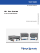
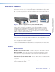
About the IPL Pro Series Figure 1. PRELIMINARY The IPL Pro Series Control Processors integrate Ethernet connection into AV systems to allow users to remotely control, monitor, and troubleshoot AV equipment, including display devices and switchers, source devices, and various other items such as lights, a projector lift, or a screen motor. They can be used in a distributed control system environment or as stand-alone control processors.
• Global compatibility — The IPL uses industry standard Ethernet communication protocols, including DHCP, DNS, HTTP, HTTPS, ICMP, NTP, SFTP, SMTP, SNMP, SSH, TCP/IP, and UDP/IP. • Embedded web pages — The IPL embedded web pages include online diagnostics and monitoring of basic features.
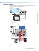
Application Diagrams The following figures shows examples of types of devices that can be connected to some of the ports on the IPL Pro Series control processors. Flat Panel Display MODEL 80 Extron IPL Pro S1 IP Link Pro Control Processor POWER 12V 0.
Device Control • An RS-232 or Ethernet driver file can be downloaded from the extensive Extron driver selection from the Extron website (http://www.extron.com/download/index.aspx). The driver is saved to a folder and commands from the driver are incorporated into the configuration file for the control processor and any touchpanels that will work with it. The configuration file is built and uploaded to the IPL via GC.
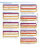
This section covers the following material: • Setup Checklist: How to Proceed With Installation — A checklist of tasks to guide you through installation • Network Communication Setup — A flowchart guide to network settings configuration • Front Panel Features — Locations and some descriptions of items on the front panel • Mounting the IPL Pro Series — Brief guidelines for mounting • Rear Panel Features and Connections — Locations, descriptions, and cabling notes for rear panel features and correspo
Mount and Cable All Devices Mount the unit to a rack or furniture (see Mounting the IPL Pro Series on page 10). Cable devices to the control processor (see Rear Panel Features and Connections starting on page 11). Connect power cords and power on all the devices. Set up the Control Processor and Touchpanels for Network Communication PRELIMINARY Connect the PC that you will use for setup, the control processor, and touchpanels to the same Ethernet subnetwork.
Network Communication Setup Network setup is essential prior to configuration. Use the flowchart as a guide to setting up the control processor for network use. Network Communication Setup, Connected/Online Method Connect the control processor and PC to the same LAN and apply power. Do you know the MAC address? PRELIMINARY Open the Toolbelt utility in Global Configurator (GC Professional or GC Plus mode). ToolBelt displays a list of all IP Link Pro devices connected to the network.
Front Panel Features Examples of front panel features are shown at right. The quantity and location of ports and Power corresponding front panel LEDs LED differ among IPL models. However, the functions of each type of port and their LEDs are identical for all models. NOTE: The control processor must be set up in order to function.
Mounting the IPL Pro Series Mounting Options UL Rack Mounting Guidelines The following Underwriters Laboratories (UL) guidelines pertain to the safe installation of the IPL Pro Series in a rack. 1. Elevated operating ambient temperature — If installed in a closed or multi-unit rack assembly, the operating ambient temperature of the rack environment may be greater than room ambient temperature.
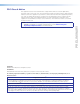
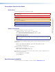
Rear Panel Features and Connections ATTENTION: Installation and service must be performed by experienced personnel. ATTENTION: L’installation et l’entretien doivent être effectués par du personnel expérimenté. The quantity of ports and corresponding front panel LEDs differs among IPL models, but the functions of each type of port and their LEDs are identical for any model that includes that type of port. POWER 12V 0.
Power Connections Power input connector (external power supply) — Connect the IPL to the included 12 VDC power supply here, then connect the external power supply to a 100 to 240 VAC power source. Power Input, External Power Supply • Connect to included 12 VDC power supply. Front Panel Rear Panel 3/16" (5 mm) Max. Ridged – Return +12 VDC input Smooth Tie Wrap Figure 7. Ground all devices. External Power Supply (12 VDC, 1 A max.
Bidirectional Control and Communication Connections and Features 5-pole COM ports, RS‑232/RS-422*/RS-485* — Use COM ports for serial control of a display or other device and to receive status messages from the connected devices. These ports can send TIP: commands from a driver file. RS-232 is the Comm-Link (CTL default mode of operation.
C LAN/PoE (IP) connectors and LEDs — To connect the IPL to an Ethernet network (so you can configure and control the IPL and the devices connected to it), plug a cable into the LAN RJ-45 socket and connect the other end of the cable to a network switch, hub, router, or PC connected to a LAN or the Internet. The IPL Pro Series control processors accept power over Ethernet (PoE) through the LAN port. Both an external power supply and PoE can be connected to the control processor simultaneously.
Resetting the Unit ATTENTION: • Review the reset modes carefully. Using the wrong reset mode may result in unintended loss of flash memory programming, port reassignment, or a unit reboot. • Étudier de près les différents modes de réinitialisation. Appliquer le mauvais mode de réinitialisation peut causer une perte inattendue de la programmation de la mémoire flash, une reconfiguration des ports ou une réinitialisation de l’unité.
Project Recovery Activation Result Purpose and Notes To start the Use Factory Firmware reset mode and replace firmware: 1. On the control processor, hold down the recessed Reset button while applying power to the unit. Hold the button down until the Power LED flashes twice. The control processor enters factory firmware mode, and the LED flashes quickly. 2. Upload new firmware to the unit as desired (see Updating the Firmware on page 38 for details).
Activation Result Purpose and Notes To reset all IP settings: 1. Hold down the Reset button for about 6 seconds until the Power LED blinks twice (once at 3 seconds, again at 6 seconds). 2. Release and press Reset momentarily (for <1 second) within 1 second*. * Nothing happens if the momentary press does not occur within 1 second. Reset All IP Settings mode: • Sets the IP address back to factory default (192.168.254.250) • Sets the subnet back to factory default (255.255.255.
This section of the guide is divided into the following topics: • Configuration and Control: an Overview • Basic Setup Steps: a Guide to this Section and Other Resources • Downloading the Software and Getting Started • Troubleshooting Configuration and Control: an Overview An IPL must be configured before use in order to recognize and accept commands and pass them on to the controlled devices.
Basic Setup Steps: a Guide to this Section and Other Resources NOTE: GC projects can be created offline and uploaded to the hardware at a later date. Follow the steps in Setup Checklist: How to Proceed With Installation starting on page 6. The overall process for setting up a control processor is as follows: See “Network Communication Setup” in this guide. Configure the IP settings of the control processor and the TouchLink Pro touchpanels.
Downloading the Software and Getting Started GC software updates and a large variety of device drivers can be downloaded from the Download page on the Extron website (http://www.extron.com/download/index.aspx). When you locate the desired software or driver package, follow the on-screen directions to download and install it.
3. For software, click on the link for the specific software that you need. A software product page opens that provides a description of the software package, a list of system requirements, a list of features, and access to the release notes, in addition to a download link. For drivers, select a product name from the drop-down list. For drivers, navigate through the alphabetically arranged list to select and download a driver for a specific device. Via links from search results 1.
Using GC Professional and GC Plus: Helpful Tips • The IPL Pro Series Setup Guide is shipped with the unit, and it lists available resources (software, drivers, instructions). It includes a quick reference to the front and rear panel features, and covers basic hardware installation. • The Global Configurator Help file provides a wealth of information on settings and how to use the software, itself.
Troubleshooting Turn on the input devices (DVD players, VCRs, PCs, and other sources), output devices (display screens, projectors), the IPL Pro control processor, and the PC and touchpanel. Touch a configured button on the touchpanel. If an input or output AV device cannot be remotely controlled (does not respond as expected), check the following: • Ensure that all devices are plugged in. • Make sure that each device is receiving power.
Reference Information • Glossary • File Types: a Key to Extron-specific File Names • Licensed Third Party Software Used in the Control Processors Full product specifications are available via the IPL Pro Series product pages at www.extron.com. Glossary 10/100Base-T Ethernet which uses unshielded twisted pair (UTP - CAT 5, CAT 5e, CAT 6) cable, where the amount of data transmitted between two points in a given amount of time is equal to either 10 Mbps or 100 Mbps.
HTTP (Hypertext Transfer Protocol) A network protocol based on TCP/IP that is used to retrieve hypertext objects from remote web pages and allows servers to transfer and display web content to users. HTTPS (Hypertext Transfer Protocol Secure) A communications protocol for secure communication over a computer network. It allows web servers to transfer and display web content to users securely. All transferred data is encrypted so that only the recipient is able to access and read the content.
SSH (Secure Shell) SSH is a network protocol for secure data communication and providing various secure network services between two networked computers. SSH creates a secure channel over an insecure network to connect client and server devices. It allows confidential communications of passwords and similar data over public or otherwise insecure networks. Static IP An IP address that has been specifically (instead of dynamically—see DHCP) assigned to a device or system in a network configuration.
File Types: a Key to Extron-specific File Names • ______.eff — This is an Extron firmware update file. See the Firmware Updates section starting on page 29 for details on firmware updates. • ___.eir — These are IR driver files containing infrared commands. There is a separate .eir file for each device the IPCP controls via infrared communication. This is also the type of file created during IR learning.
Licensed Third Party Software Used in the Control Processors The control processors use various licensed third party software packages during operation. To view details about third-party packages and associated licensing, click the License Information button in the internal web pages of the control processor. A License Information window opens. To view a copy of a listed package license, in the License Information window, click the link in the License column for the relevant package.
Firmware Updates • Determining the Firmware Version — How to find the current firmware version • Updating the Firmware — How to download and replace firmware PRELIMINARY If the need arises, you can replace the IPL firmware without opening the unit or changing firmware chips.
Updating the Firmware Firmware upgrade tools require the PC and the control processor to both be connected to an Ethernet network. The instructions for each method of updating the IPL firmware assume you have installed the appropriate software on your PC first. • Check the Extron website (www.extron.com) for firmware-related documents, instructions, patch files, and new firmware files before loading new firmware into the control processor.
Symbols D F .eff downloading the file for a firmware upgrade 30 file type description 27 .eir file type description 27 .gc2 file type description 27 .gcplus file type description 27 .gcpro file type description 27 .gcz file type description 27 .gdl file type description 27 .
P T IP address resetting to default (Reset All IP Settings mode) 17 IR and RS-232 device control 5 IR drivers IR driver file type (.
Extron Warranty Extron Electronics warrants this product against defects in materials and workmanship for a period of three years from the date of purchase.