
Setup Guide Owner manual

5
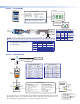
Control — Serial (COM)
G
Tx Rx
RTS CTS
COM 1
G
Tx Rx
RTS CTS
COM 4
COM
312 645
RTS
CTS
Tx
Rx
COM
RTS
CTS
Tx
Rx
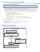
NOTE: If you use cable that has a drain wire, tie the drain wire to ground at both ends.
Strip wires
3/16" (5 mm)
max.
Transmit (Tx)
Receive (Rx)
Projector, Panel
Display, PC, or
Other RS-232,
RS-422, or
RS-485 Device
Request to send
Clear to send
Transmit
Rx Receive
Tx
CTS
RTS
G Ground
Tx
R
Front Panels
5-pole COM
(RS-232, RS-422*, RS-485*)
*See the Serial Options
table for which port
supports which standards.
Select protocol via software.
COM port default protocol:
• 9600 baud
• 8 data bits • 1 stop bit
• no parity • no ow control
NOTE: The 5-pole COM ports support both
hardware and software ow control.
Heat ShrinkHeat Shrink
Over Shield Wires
To
5-pole
COM port
RTS =
Request to Send
CTS = Clear to Send
Tx = Transmitting Data
Rx = Receiving Data
Serial (COM) Ports
Rear Panels
RS-232
Tx
Rx
Ground
RTS
CTS
RS-422*
Tx-
Rx-
Ground
Tx+
Rx+
RS-485*
Ground
5-pole COM Pin Configurations
Data-
(pins 1 & 2
tied together)
Data+
(pins 4 & 5
tied together)
Pin
1 (Tx)
2 (Rx)
3 (G)
4 (RTS)
5 (CTS)
*See the Serial Options table of supported
formats for each port.
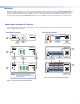
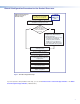
Control — LAN (Ethernet)
1000
LINK
ACT
LAN / PoE
I
PL PR
O
S
6
5-
5
-A6-
XX-XX-XX
##
#
## E######
5
5
-A6-XX-XX-XX
RJ-45
Connector
Insert Twisted
Pair Wires
Pins:
12345678
Rear Panel Front Panel
Link
LED
Activity
LED
1000 Mbps
Connection
Network is
active.
Data is being
sent/r
eceived.
Ethernet
PC
Touchlink Pro
Touchpanel
Extron Devices
(Switchers, Scalers)
TCP/IP
Network
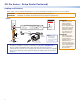
Straight-through Cable
(for connection to a switch, hub, or router)
End 1 End 2
Pin Wire Color Pin Wire Color
1 white-orange 1 white-orange
2 orange 2 orange
3 white-green 3 white-green
4 blue 4 blue
5 white-blue 5 white-blue
6 green 6 green
7 white-brown 7 white-brown
8 brown 8 brown
Crossover Cable
(for direct connection to a PC)
End 1 End 2
Pin Wire Color Pin Wire Color
1 white-orange 1 white-green
2 orange 2 green
3 white-green 3 white-orange
4 blue 4 blue
5 white-blue 5 white-blue
6 green 6 orange
7 white-brown 7 white-brown
8 brown 8 brown
T568B T568AT568BTIA/EIA-T568B
LAN/PoE (Ethernet)
Default protocol:
• IPL IP address: 192.168.254.250
• Gateway IP address: 0.0.0.0
• Subnet mask: 255.255.255.0
• DNS address: 127.0.0.1
• DHCP: off
• Link speed and duplex level:
autodetected
• Data rates: 10/100/1000Base-T
Power over Ethernet (PoE):
If PoE is available, the IPL uses PoE.
If PoE is dropped (disconnects), the
IPL switches seamlessly to the
external 12 VDC power supply, if it
is installed.
Default login credentials:
• Username: admin
• Password: extron
The control processor is assigned a unique user hardware ID number (MAC address) (for example,
00-05-A6-05-1C-A0). You may need this address during configuration of the control processor. A
label that indicates the MAC address is located on the rear panel of the unit.
NOTE: The supported serial formats
vary depending on the COM port,
as shown at right.
RS-232
Only
RS-232, RS-422,
or RS-485
Serial Options
Model COM Port
1
IPL Pro S1
1
2, 3
IPL Pro S3
1
2, 3, 4, 5, 6
IPL Pro S6
MAC: 00-05-A6-XX-XX-XX
S/N: ####### E######
00-05-A6-XX-XX-XX
MAC: 00-05-A6-XX-XX-XX
S/N: ####### E######
MAC
Address