
Setup Guide User guide

8
IPCP Pro Series • Setup Guide (Continued)
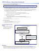
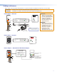
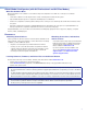
Control, Unidirectional — Flex I/O or Digital I/O
1 234G
DIGITAL I/O
FLEX I/O
3214G
FLEX
I/O
34
21
I/O
3
1
4
2
Ground
Wire
Nut
Device 4
Device 3
Device 2
Device 1
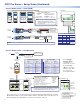
Share the same ground among
I/O connections.
Digital I/O (digital input/output)
Congure each port as as a digital input or output,
with or without +5 VDC pull-up.
Use these ports to:
• Monitor or trigger events and functions (toggle relays,
issue commands, send e-mail), once congured.
• Power LEDs, incandescent lights, or other devices
that accept a TTL signal.
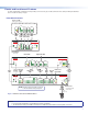
Flex I/O (digital input/output or analog input)
Congure each port as an analog input or as a digital
input or output with or without +5 VDC pull-up.
(Switches, sensors,
LEDs, relays, or
similar items)
Switch,
Sensor
2
1
3
4
G
Heat
Shrink
Over
Shield
Wires
Rear Panel Front Panel
Digital I/O
LEDs
Light when the
corresponding
ports are active.
Flex I/O LEDs
Light when the
corresponding
ports are active.
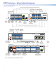
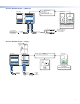
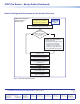
Control — Volume
VCG
10V 50mA
GCV
REMOTE
10V 50mA
GCV
10V
REMOTE
VOL/MUTE
REMOTE
VOL/MUTE
10V 50mA
G
STANDBY
10V 50mA
GCV
VCG
VOL
Ground (Gnd)
C
G
V
Ground
Reference voltage
C
G
Control voltage
V
Reference voltage input (from amplier) – This allows the IPCP Pro to detect when the amp is present.
Control voltage (variable output to amp from IPCP Pro) – This signal controls the amp volume.
Control voltage output:
0 - 10 VDC
Reference
voltage: ≤10 VDC
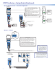
Example:
Connecting to
Extron Amplifiers
IPCP Pro
Rear
Panel
Rear Panel
Volume Control
This port can be used to control the volume and mute or
unmute the audio for Extron half rack width audio ampliers.
• Connect to an Extron audio ampier to permit volume
control via touchpanel controls, macros, or schedules.
• Do not exceed 10 VDC input voltage.
Congure the maximum and minimum voltage limits. Set
Soft Start mode off or on (default) . Soft Start mode allows
volume to gradually increase from mute to the previous level
after muting or power-on to prevent loud audio bursts
C or
VOL/MUTE
V or 10V G or
MPA 401 Series
MPA 181T,
MP 101 Series
MPA 152MPA 152 Plus
XPA 1002
NOTE:
Use shielded cable and
place the control processor
as close as possible to the
amplier to avoid picking up
background noise via the
cable. Ideal cable length is
six feet or less.
NOTE: When audio mute is active, the
control processor sets output voltage
to
0 VDC, even if the voltage range
(minimum and maximum voltage
limits) has been set to levels above
zero, such as 2 V to 8 V.