
Setup Guide User guide

5
Cabling and Features
Attach cables using the following wiring diagrams as a guide. Full details are available in the IPCPPro Series User Guide.
ATTENTION: Installation and service mus t be performed by experienced personnel.
ATTENTION: L’installation et l’entretien doivent être effectués par du personnel expérimenté.
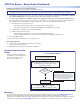
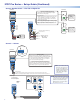
Power Input — External
POWER
12V
x.xA MAX
R
Ground
all devices.
External
Power Supply
(12 VDC, 1 A max.)
– Return
+12 VDC input
Ridged
Smooth
1A MAX
100-240V 50-60Hz
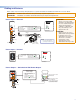
Power Input, External Power Supply
• Front panel LED ( ) blinks during
boot-up and lights when the IPCP
is powered and operational.
• Connect to
included 12 VDC
power supply.
Rear
Panel
Front Panel
NOTE:
Check the polarity of
the power supply before
connecting it to the IPCP.
Ridged
Smooth
Tie Wrap
3/16"
(5 mm)
Max.
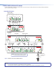
Power Input — Internal
R
1.2A MAX
100-240V 50-60Hz
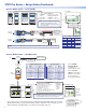
Power Input, Internal Power Supply
• Front panel LED ( ) blinks
during boot-up and lights
when the IPCP receives power.
• Connect to 100 to
240 VAC.
Rear Panel
Front Panel
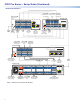
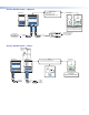
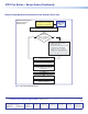
Power Output — Switched 12 VDC Power Output
21
LIMIT
SWITCHED
12 VDC
OVER
43
12 VDC
SWITCHED 12 VDC
40W MAX TOTAL
3 4
1 2
Lights if total power draw
is 44-48 watts.
Lights if total power draw
exceeds 48 watts.
Power output shuts of
f for
a period to allow the user
to correct the overload.
Switched 12 VDC
Power Output
• 12 VDC, 40 watts (max.)
= total output for all four ports
combined
• Corresponding front panel
green LEDs ( ) light when
power is available at each port.
3/16"
(5 mm)
Max.
Rear
Panel
Front
Panel
Tie Wrap
ATTENTION:
Always use a power supply
supplied or specified by Extron.
Use of an unauthorized power
supply voids all regulatory
compliance certification and
may cause damage to the
supply and the unit.
ATTENTION:
Utilisez toujours une source
d’alimentation fournie par Extron.
L’utilisation d’une source
d’alimentation non autorisée
annule toute conformité
réglementaire et peut
endommager la source
d’alimentation ainsi que l’unité.