Preliminary Operation Manual IN3600 Series 6-Input Switchers IN3606 RGBS Switcher IN3654 / IN3656 RGBHV Switchers IN3666 VGA Switcher ®
Installation and Safety Instructions For Models without a Power Switch: The socket outlet shall be installed near the equipment and shall be accessible. For Models with 110 / 220V Power Selector: Caution: Before applying power to this unit, the voltage selector must be set to the appropriate setting to match local A/C line voltage. Improper setting of the voltage selector may cause damage to the unit and create a potential fire hazard.
Installations und Sicherheitshinweise Für Geräte ohne Netzschalter: Die Netzsteckdose soll in de Nähe des Gerätes installiert und frei zugänglich sein. Für Geräte mit 110 / 220V Spannungswähler: Achtung: Bevor Sie dem Gerät Spann ung zuführen, muß der Spannungswähler entsprechend der Spannung des lokalen Wechselspannungsnetzes eingestellt werden. Die falsche Stellung des Spannungswählers kann eine Beschädigung des Gerätes und möglicherweise ein Feuer verursachen.
CE COMPLIANCE All products exported to Europe by Inline, Inc. after January 1, 1997 have been tested and found to comply with EU Council Directive 89/336/EEC. These devices conform to the following standards: EN50081-1 (1991), EN55022 (1987) EN50082-1 (1992 and 1994), EN60950-92 Shielded interconnect cables must be employed with this equipment to ensure compliance with the pertinent Electromagnetic Interference (EMI) and Electromagnetic Compatibility (EMC) standards governing this device.
1 DESCRIPTION The IN3600 Series includes four high performance analog video switchers with four or six inputs and one output. The IN3600 Series switchers are designed to route several high resolution source signals to an attached desktop data monitor, presentation monitor or data projector. Users may select the desired input channel using front panel buttons or via remote control using an optional wired remote or control system.
2 INSTALLATION This section offers step-by-step instructions for installing IN3600 Series switchers. 1. Connect all sources to the input connectors. Unused inputs do not need to be terminated. 2. An interface may be required for each computer video signal source in order to split off a signal for each local monitor, bring all signals into the appropriate format, and amplify the signal to compensate for long input/output cable runs. 3. Connect the IN3600 Series switcher output to the display device. 4.
3 Programming Options ♦ RGB Delay Only H and V inputs of a particular input is switched immediately. This is to allow for resizing and syncing of monitors before the RGB picture elements are sent. The RGB inputs are switched a time period afterwards. This time period is programmable in half second increments from one half second to 7.5 seconds.
4 To set Input Scan Options - Hold down INPUT3 button during power-up: A. BLANK LED goes solid B. Letting go of INPUT3, BLANK LED flashes C. Press one of the INPUT buttons to select inputs to scan: INPUT1 Disable scanning (If entered, skips to end) INPUT2 Scan Inputs 1 to 2 INPUT3 Scan Inputs 1 to 3 INPUT4 Scan Inputs 1 to 4 (And for the IN3656 switcher:) INPUT5 Scan Inputs 1 to 5 INPUT6 Scan Inputs 1 to 6 (INPUT1 LED will go on to show scan enabled and 2-6 LED will go on to show to what input) D.
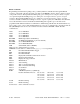
5 RS232 Commands Programming and information polling is also possible by RS232 communication through the RS232 connector on the back of the unit. Connection is made via an IN9317 connector wired to either a 9-pin D or 25-pin D connector. The input labeled GND (pin2) goes to either pin 7 of a 25 pin connector or pin 5 of a 9 pin. The input labeled TX (pin1) goes to either pin 3 of a 25 pin connector or pin 2 of a 9 pin connector.
6 ScantX X=Scan Time between Channels (i.e. [SCANT12.5] would set the scan time to 12.5 seconds) Possible allowable times are: 2.5 seconds 5.0 seconds 7.5 seconds 10.0 seconds 12.5 seconds 15.0 seconds 17.5 seconds 20.0 seconds 22.5 seconds 25.0 seconds 27.5 seconds 30.0 seconds 32.5 seconds 35.0 seconds 37.5 seconds REMOTE CONTROL OPERATION The IN3600 Series switchers have a REMOTE CONTROL port which allows these units to be remotely controlled.
7 IN3546R STEREO AUDIO SWITCHER The IN3546R Stereo Audio Switcher may be attached to the IN3600 Series via the REMOTE CONTROL port. This provides a +5V power supply for the IN3546R Switcher and a control link. When the IN3546R is attached to the control port using an IN9112 control link cable, the IN3546R will automatically switch to the appropriate input channel, mirroring the input selected on the attached switcher and adding audio-follow-video capability to the switcher.
8 TROUBLESHOOTING The display device connected to the switcher output has a bad/scrambled image. Solution 1: The display device connected to the output of the switcher may not be compatible with the computer output. 640 x 480 VGA runs at 31.5 KHz, but SVGA, XGA and SXGA modes can be as high as 48 - 80 KHz and higher depending on the refresh rate. MACII/Quadra computers sense what monitor is connected and configure themselves accordingly, with horizontal scan rates ranging from 24.48 to 68.9 KHz.