OPERATION MANUAL Installation Interface Series IN2116 Table Mountable Interface
Installation and Safety Instructions For Models without a Power Switch: The socket outlet shall be installed near the equipment and shall be accessible. For Models with 110 / 220V Power Selector: Caution: Before applying power to this unit, the voltage selector must be set to the appropriate setting to match local A/C line voltage. Improper setting of the voltage selector may cause damage to the unit and create a potential fire hazard.
Installations und Sicherheitshinweise Für Geräte ohne Netzschalter: Die Netzsteckdose soll in de Nähe des Gerätes installiert und frei zugänglich sein. Für Geräte mit 110 / 220V Spannungswähler: Achtung: Bevor Sie dem Gerät Spann ung zuführen, muß der Spannungswähler entsprechend der Spannung des lokalen Wechselspannungsnetzes eingestellt werden. Die falsche Stellung des Spannungswählers kann eine Beschädigung des Gerätes und möglicherweise ein Feuer verursachen.
CE COMPLIANCE All products exported to Europe by Inline, Inc. after January 1, 1997 have been tested and found to comply with EU Council Directive 89/336/EEC. These devices conform to the following standards: EN50081-1 (1991), EN55022 (1987) EN50082-1 (1992 and 1994), EN60950-92 Shielded interconnect cables must be employed with this equipment to ensure compliance with the pertinent Electromagnetic Interference (EMI) and Electromagnetic Compatibility (EMC) standards governing this device.
Table of Contents Product Overview ................................................................................................2 Description ........................................................................................................2 Product Features ...............................................................................................2 Compatibility........................................................................................................4 Input .....................
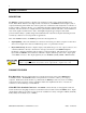
2 Product Overview DESCRIPTION The IN2116 is a high performance computer video interface for analog video signals including VGA, SVGA, XGA, MAC, SUN and other high-resolution workstations. The IN2116 combines high-resolution computer interfacing and modular A/V connector plates into a unit that mounts neatly under a conference or boardroom table, computer workshop, or a podium using integral mounting brackets and (4) #6 wood screws (included).
3 Modular A/V Connector Plates - In addition to its interface capability, the IN2116 also acts as a modular A/V connector plate. The IN2116 front panel accepts up to four A/V connector modules, available with a variety of popular connectors. Two of the most commonly used modules for table mounted installations are the RJ45 jack (for quick access to the computer network) and the 3.5mm stereo mini or dual RCA jacks (to connect the computer’s sound card output to the room’s sound system).
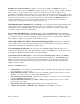
4 Compatibility INPUT The IN2116 will accept high-resolution video signals from virtually any computer that outputs an analog video signal (VGA, SVGA, XGA, MAC, SUN, SGI and other high-resolution computers) at virtually any refresh rate. Input signal compatibility parameters are: Video Signal: Analog RGB Video Signal Format: RGBHV, RGBS, RGsB* Horizontal Frequency Range: 30 KHz to 130 KHz Vertical Refresh Rates: 30 Hz to 120 Hz * The IN2116 will operate with RGsB input signals.
5 ADAPTER / EXTENSION CABLES FOR INPUT AND LOCAL MONITOR OUTPUT The IN2116 has 15-pin HD VGA-type connectors for input and local monitor output.
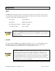
6 Installation This section offers step-by-step instructions for installing the IN2116 (see Application Diagram on page 7). 1. Set the dipswitches for the requirements of your installation (see Dipswitch Settings on page 9). The IN2116 factory default output format is RGBHV. If your display device, routing system or cabling requires a different format, use the dipswitches to change the output signal to RGBS or RGsB as desired. 2.
7 IN2116 APPLICATION DIAGRAM IN7000-5/IN7100-5/IN7200-5 IN8800 RGBHV Instalation Cable Matrix Switcher Data Projector/ Presentation Monitor IN7200-1 Video Cable Sound System IN7200-1 Video Cable IN7000-5/IN7100-5/IN7200-5 RGBHV Instalation Cable REAR VIEW TECHNICAL SUPPORT: (714)921-4100 (800)882-7117 www.inlineinc.com FUSE; 8 A; 250 V; TIME DELAY 125 VAC; 6.4 A; 47-63 HZ OUTPUT HORIZONTAL/ VERTICAL COMPOSITE SYNC SYNC BLUE GREEN RED MADE IN U.S.A.
8 IN2116 FRONT PANEL CONNECTORS AND CONTROLS Power Input Connector Indicator Stereo Audio Input A/V Connector Modules 2116 MAXIMUM POWER: 800W High Resolution Video Interface LOCAL MONITOR INPUT HORIZONTAL POSITION Horizontal Position Control Local Monitor Output (Buffered) FRONT VIEW REAR VIEW FUSE; 8 A; 250 V; TIME DELAY 125 VAC; 6.4 A; 47-63 HZ TECHNICAL SUPPORT: (714)921-4100 (800)882-7117 www.inlineinc.com OUTPUT HORIZONTAL/ VERTICAL COMPOSITE SYNC SYNC BLUE GREEN RED MADE IN U.S.
9 DIPSWITCH SETTINGS Most installations will not require any changes to the dipswitch settings, and the IN2116 will generally be operated with the factory default settings. The factory default and specialized dipswitch settings are indicated below.
10 IN9370 AUDIO BUFFER MODULE The IN2116 can be ordered with a IN9370 audio buffer module. This factory installed optional module takes an unbalanced stereo audio input, buffers the signal and outputs it as balanced stereo audio.
11 AUDIO / VIDEO / PHONE / DATA / SWITCH / COMPUTER CONNECTOR MODULES Modular A/V Connector Plates & Accessories for: IN2111 Series / IN2112 Series / IN2114 Series / IN2116 / IN3260 / IN9166 / IN9167 / IN9168 Connector Module Black/White Description Front Connector / Termination Back Connector / Termination Module Size None (2) BNC Female 4 Bare Wires (2) Solder Lug Terminal (2) Solder Lug Terminals (3) Solder Lug Terminals (3) Solder Lug Terminals Single Single Single Single Single (5) Solder Lug
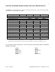
12 Connector Module Black/White IN9375B / IN9375W IN9376B / IN9376W IN9377DB / IN9377DW IN9378B / IN9378W IN9381B / IN9381W IN9382B / IN9382W IN9383B / IN9383W IN9384B / IN9384W IN9385B / IN9385W IN9386B / IN9386W IN9387B / IN9387W IN9388B / IN9388W IN9389B / IN9389W IN9394DB / IN9394DW IN9395DB / IN9395DW IN9396DB / IN9396DW Front Connector / Terminal Description Back Connector / Terminal Module Size (2) Keyboard / Mouse Connectors A/V Super Module with Barrel Connectors: (2) RCA - Audio & (1) RCA
13 Specifications Input Connector Type RGB Video Signals Input Impedance Sync Signals Horizontal Scan Rate Vertical Scan Rate Output Buffered Local Monitor Stereo Audio Output with IN9370 Installed (Buffered) Main Output Output Signal Formats RGB Signals Bandwidth Rise and Fall Times Gain Sync Signal Horizontal Pulse Width Vertical Pulse Width Controls External Internal Dimensions Size (including faceplate) Shipping Weight Power Power Supply Front Panel A/C Outlet 15-pin HD male - standard VGA pin-outs An
14 Parts Included (1) IN2116 Table Mountable Installation Interface (1) IN9334 3/32 Allen Wrench for IN2116 Connector Module Set Screws (1) IEC Power Cable (1) Operation Manuel Required Accessories (Ordered Separately) Input and Local Monitor Adapter and Extension Cables: VGA: IN8000 Series 15-pin HD male to 15-pin HD female, various lengths from 3’ to 100’ For Other Computers: See list on page 4 Optional Accessories Balanced Audio Module IN9370: Audio Buffer Module - converts unbalanced stereo audio signal
15 Troubleshooting The display device connected to the IN2116 output has a bad / scrambled image. Solution 1: Verify that the correct input cable is being used (see list on page 5). Solution 2: The display device connected to the output of the interface may not be compatible with the computer output. Standard 640 x 480 VGA runs at 31.5 KHz, and SVGA can be as high as 48 - 58 KHz, depending on the vertical refresh rate.
16 The output image is doubled, with two images displayed side-by-side. Solution: The display device may not be compatible with the horizontal scan rate of the computer. This problem often occurs when a 31.5 KHz VGA signal is sent into an RGB monitor that is only compatible with signals at 15.75 KHz. If problems persist, call INLINE Technical Services at (800) 882-7117 for further assistance. Warranty ♦ INLINE warrants the equipment it manufactures to be free from defects in materials and workmanship.
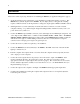
12.50“ 1.80“ IN2116 Front View 11.75“ 1.195“ Mounting Holes: 0.156“ / 4 mm Diameter (4) #6 Wood Screws Included 12.125“ 0.187“ 4.78“ 2.