
User Guide


Programming
Guide
This section describes SIS command control of the IN1508, including:
• RS-232 Port
• Host-to-Switcher Instructions
• Switcher-Initiated Messages
• Switcher Error Responses
• Using the Command/Response Tables
RS-232 Port
The rear panel Remote 9-pin D female connector (figure 35) can be connected to the RS-232
serial port output of a host device such as a computer running the HyperTerminal utility or a
control system. This connection makes software control of the switcher possible.
51
96
Female
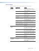
RS-232FunctionPin
1
2
3
4
5
6
7
8
9
—
TX
RX
—
Gnd
—
—
—
—
Not used
Transmit data
Receive data
Not used
Signal ground
Not used
Not used
Not used
Not used
Figure 35. Remote connector pin arrangement
The protocol is 9600 baud, 8-bit, 1 stop bit, no parity, and no flow control.
Host-to-Switcher Instructions
The switcher accepts SIS commands through the RS-232 port. SIS commands consist of one
or more characters per field. No special characters are required to begin or end a command
character sequence. When a command is valid, the unit executes the command and sends
a response to the host device. All responses from the unit to the host end with a carriage
return and a line feed (CR/LF =
]
), which signals the end of the response character string. A
string is one or more characters.
IN1508 • Programming Guide 51