
Setup Guide


N For full installation, configuration, and operation details, refer to the
IN1508 User’s Manual, available at www.extron.com.
This guide provides quick start instructions for an experienced installer to set up and
operate the Extron IN1508 Scaling Presentation Switcher.
Installation and cabling
50/60Hz
100-240V 50-60Hz
I
N
P
U
T
VID
VID
YC
YC
Y
B-Y
R-Y
RGB
DVI
RS-232
1
2 4
5
3
L
1 2 3 4 5
6
7
R
AUDIO INPUT
8
L
A
B
R
OUTPUT
L R
OUTPUT
RGB
Y, B-Y, R-Y
7
8
RGB
LIS TED
1T2 3
I.T. E.
C
U S
6
2 5 9843
1 6 12117
10
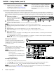
Connections
a
AC power connector
g
Output 15-pin HD connector
b
Inputs 1 and 2 composite video BNC connectors
h
Audio Inputs 1 through 5 RCA connectors
c
Inputs 3 and 4 S-video mini-DIN connectors
i
Audio Inputs 6 through 8 3.5 mm mini stereo jacks
d
Input 5 component video BNC connectors
j
Audio Output A RCA connectors
e
Inputs 6 and 7 RGB video 15-pin HD connectors
k
Audio Output B captive screw connector
f
Input 8 DVI video connector (DVI-D only)
l
RS-232 9-pin D connector
Step 1 — Mounting
Turn off or disconnect all equipment power sources. For tabletop use, affix the rubber feet. For
optional rack mounting, secure the supplied brackets (see image at right) and mount in a rack.
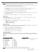
Step 2 — Video inputs and output
a. Inputs 1 and 2 — Connect composite video
sources to these female BNC connectors.
b. Inputs 3 and 4 — Connect S-video sources
to these 4-pin mini DIN connectors.
c. Input 5 — Connect a component video
(YUVi, YUVp, HDTV) source to these
female BNC connectors.
d. Inputs 6 and 7 — Connect RGB video sources to
these 15-pin HD connectors.
e. Input 8 — Connect a single link of DVI-D video
to this DVI-I connector.
f. Output — Connect an RGB or component video
display to this 15-pin HD output female connector.
Step 3 — Audio inputs and outputs
a. Audio Inputs 1 through 5 RCA connectors —
Connect stereo or mono audio sources.
b. Audio Inputs 6 through 8 3.5 mm mini jacks — Connect computer
audio sources.
c. Output A RCA audio connectors — Connect a stereo or mono audio
device (receiver, amplifier, or the like).
— OR —
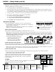
Output B audio captive screw connector — Connect a stereo or mono
audio device (receiver, amplifier, or the like); wire the connector as shown
at right.
68-791-50
Rev. A 04 10
IN1508 – Setup Guide
100-240V 50-60Hz
I
N
P
U
T
VID
VID
YC
Y
B-Y
C-Y
RGB
DVI
1
2 4
5
3
L
2 3 4
5
6
7
R
AUDIO INPUT
L
A
B
R
OUTPUT
L
R
OUTPUT
RGB
Y, B-Y, C-Y
8
7
RGB
6
LISTED
1T23
I.T.E.
C
U S
I
N
P
U
T
VID
VID
1
2
YC
YC
4
3
YC
Y
B-Y
R-Y
5
RGB
7
RGB
6
DVI
8
L
1 2 3 4 5
6
7 8
R
AUDIO INPUT
L
A
B
R
OUTPUT
L R
OUTPUT
RGB
Y, B-Y, R-Y
For unbalanced audio output, connect
the sleeve(s) to the ground contact.
DO NOT connect the sleeve(s) to the
negative (-) contacts).
Unbalanced Stereo OutputBalanced Stereo Output
CAUTION
Tip
NO GROUND HERE.
Sleeve(s)
Tip
NO GROUND HERE.
Tip
Ring
Tip
Ring
L R
L R