Installation and Maintenance Manual Preliminary HSA 822MS Motorized Hideaway Surface Access Enclosure www.extron.com Extron Electronics, USA Extron Electronics, Europe Extron Electronics, Asia Extron Electronics, Japan 1230 South Lewis Street Anaheim, CA 92805 USA 714.491.1500 Fax 714.491.1517 Beeldschermweg 6C 3821 AH Amersfoort The Netherlands +31.33.453.4040 Fax +31.33.453.4050 135 Joo Seng Road, #04-01 PM Industrial Building Singapore 368363 +65.6383.4400 Fax +65.6383.
Precautions Safety Instructions • English This symbol is intended to alert the user of important operating and maintenance (servicing) instructions in the literature provided with the equipment. This symbol is intended to alert the user of the presence of uninsulated dangerous voltage within the product's enclosure that may present a risk of electric shock. Caution Read Instructions • Read and understand all safety and operating instructions before using the equipment.
Table of Contents About the HSA 822MS Hideaway Enclosures .......... 1-2 Features ...................................................................................... 1-5 Chapter 2 • Installation ............................................................. 2-1 Installation Overview .......................................................... 2-2 Preparing the Table .............................................................. 2-4 Preparing the HSA .........................................................
Appendix A • Reference Information ............................ A-1 Specifications ......................................................................... A-2 Part Numbers .......................................................................... A-4 HSA 822MS ............................................................................ A-4 Included parts ....................................................................... A-4 Template, replacement parts, and accessories ....................
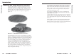
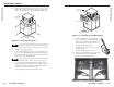
About the HSA 822MS Hideaway Enclosures The Extron HSA 822MS is a furniture-mounted, motorized architectural solution for computer video interface connector access and control. The top (table) surface of the HSA can be made from the portion of the furniture that is removed for the HSA installation to provide an inconspicuous appearance (figure 1-1). The installed enclosure fits flush within a table or podium top, storing the AAPs and connectors out of the way and out of sight.
The functionality of the HSA 822MS can be optimized with one through four RGB 580xi AAPs connected to one through four RGB 580xi Remote Interfaces (figure 1-2).
HSA 822MS 2 Chapter Two Installation Installation Overview Preparing the Table Preparing the HSA Mounting the HSA Mounting the Table Surface Making Final Adjustments Cabling and Installing the AAPs Routing the AAP Cables Cabling the Enclosure Bezels 1-6 HSA 822MS • Introduction Preliminary Preliminary Introduction, cont’d
CAUTION Installation and service must be performed by authorized personnel only. Installation Overview 11 Route and secure the AAP cables inside the enclosure. See Routing the AAP Cables on page 2-16. 12 Connect the power, RJ-45, and control and status cables to the underside of the enclosure. See Cabling the Enclosure on page 2-18. 13 Connect power cords and turn on the devices that connect to the surface access enclosure.
The preferred and recommended method for preparing the table is to have the hole cut to the exact dimensions identified in appendix A by a reputable carpenter or other craftsman. Preliminary Preliminary Installation, cont’d Preparing the Table CAUTION The opening in the table for the HSA should be cut only by licensed and bonded craftspeople. Exercise care to prevent scarring or damaging the furniture. When selecting a mounting location, be aware that the HSA 822MS is not exactly square.
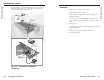
3. Remove and retain the four screws in the corners of each side’s surface of the enclosure shroud “cube” (figure 2-4). Remove the two halves of the shroud and set them aside. Remove two screws ea. side. HSA 822MS Enclosure INP SE UT LE CT CO MP UT AU DIO ER HS Remove panel. HS A Preliminary Preliminary Installation, cont’d A 82 2 82 2M S Replacement Face Plate Screws (4) under Enclosure Figure 2-5 — Removing the AAP/RJ-45 panel Remove (4) Screws (each side). 7.
. Remove the two bolts and washers that secure the tray to the underside of the HSA and remove the tray. Mounting the Table Surface 1. Mounting the HSA 1. Place the HSA upside-down over the table. Using the eight provided #8-32 wood screws and #8 washers, secure the HSA to the underside of the table (figure 2-7). Leave the screws slightly loosened for adjustment. Place the piece of table material (the surface block) that you will use as the top of the HSA upside-down on a protected surface.
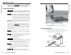
4. Firmly hold the top plate in position and drill pilot holes, each 3/32" in diameter by 1/4" deep, at each of the top plate’s four screw holes (figure 2-9). Making Final Adjustments 1. On the 10-pin control and status captive screw connector on the underside of the HSA, use a piece of wire to temporarily jumper pin 4 to pin 5 to enable the manual activation (press to activate) operation of the HSA. 2. With the unit unpowered, gently press on the surface block to retract (close) the unit.
b. 5. If necessary, slowly tighten one or more of the other adjustment screws to raise a corner or side of the surface block to horizontal. A generic limit switch assembly is shown in close-up below. The lower limit switch assembly looks similar, but is not identical to the close-up shown, but parts of the lower limit assembly are concealed from view.
8. Press on the surface block to raise and lower the platform. Double check that the surface block is centered in the cutout hole. If necessary, loosen the top plate nuts and repeat step 6. 9. Double check that the surface block is flush with the table surface. If necessary, repeat step 5. 10. Double check that the surface block is horizontal and not tipped to one side or the other. If necessary, repeat step 4. 11. On the underside of the HSA, disconnect AC power. 12.
Routing the AAP Cables Preliminary Preliminary Installation, cont’d The AAP cables must have freedom of movement to permit opening and closing the surface mount enclosure. At the same time, they need to be restrained to prevent them from rubbing against the edges of the enclosure cable access hole in the underside of the surface mount enclosure. Rubbing against the cable access hole edges can damage the cables. Route and secure the AAP cables as follows: 1.
Cabling the RJ-45 connectors Cabling the Enclosure Plug one end of a terminated CAT 5 or CAT 6 twisted pair (TP) cable into each of these RJ-45 female connectors. Connect the other end to an appropriate telecommunications or data network device or to an Extron TP product. Hardwired (USA/domestic) 2 4 8 6 An RJ-11 (telephone) plug can be connected to the RJ-45 jack. IEC (International) The bottom RJ-45 connectors match up with the AAP/RJ-45 panel RJ-45 connectors as shown in figure 2-16.
Cabling the control and status connector Plug one end of the control cable(s) into this 10-pole captive screw connector. Connect the other end of the cable(s) to a control and/or monitoring system. The following table identifies the signals on each pin of the connector.
4 5 7 6 8 The HSA 822MS ships with RJ-45/RJ-11 connector bezel plugins in a variety of colors and a black, blank Bezel bezel. To change to a different color RJ-45 connector bezel or if an RJ-45 connector is not needed or desired, replace the connector bezel plug-in on the AAP/RJ-45 panel with a bezel of a different color or a blank plug-in. See Replacing the Bezels in chapter 3.
HSA 822MS 3 Chapter Three Maintenance and Modifications Replacing an AAP Replacing the Bezels Removing and Replacing the Shroud Setting the Upper Limit Switch (Elevated Platform Height) Setting the Lower Limit Switch (Lowered Platform Height) Setting the Manual Release Switch Safety Switch — Location Only Replacing the Control Board Assembly and Power Supply Assembly 2-24 HSA 822MS • Installation Preliminary Preliminary Installation, cont’d
Installation and service must be performed by authorized personnel only. CAUTION This chapter provides the following procedures: Maintenance procedures marked with an asterisk (*) require removing the shroud from the HSA 822MS.
3. Disconnect any cables from the rear of the AAP(s) that are being replaced. 4. If an AAP cable is no longer required in your system, from the underside of the enclosure, reach into the cable access holes (figure 3-1 on page 3-2, item 3 ), and cut the tie wraps ( 5 shows the tie-downs) that route the AAP cables and network (CAT 6) cables inside the enclosure. 7. If an AAP cable is no longer required in your system, carefully pull the cable through and out the bottom of the surface mount enclosure. 8.
5. Snap the interior RJ-45 cable connectors onto the rear of the replacement RJ-45 AAP panel bezel plug-ins. 6. Replace the AAP/RJ-45 panel in RJ-45 Bezel the surface mount enclosure and Plug-in in AAP Panel secure it in place with the screws removed in step 1. If you lose an AAP/RJ-45 panel screw, four spare screws are stored in the underside of the enclosure (figure 3-1 on page 3-2, item 6 ).
4. Loosen the upper limit lock nut. 5. Rotate the upper limit set screw: Upper Limit Switch Switch (Hidden) Actuator Clockwise to lower the upper limit of platform motion. Counterclockwise to raise the upper limit of platform motion. Lower Limit Set Screw Upper Limit Lock Nut Lower Limit Switch Upper Limit Set Screw Control Board Adjustments do not take affect immediately. You must use the motor mechanism to lower and raise the platform to see the affect of your adjustment. 6.
5. Setting the Manual Release Switch Clockwise to make the manual release more sensitive. This switch’s position is properly set in the factory. The manual release switch sets the amount of pressure needed to activate the press-to-activate feature. If the switch is set too low, you may have to push too hard on the platform. If the switch is set too high, the drive mechanism may activate sporadically.
Safety Switch — Location only The safety switch (figure 3-9) stops the downward motion of platform when it encounters an obstruction to its smooth operation. If an obstruction is present that blocks the platform’s travel, the stepper motor’s carriage lifts and activates the safety switch. The HSA’s motor logic automatically reverses the platform’s motion and raises the platform to the upper position. The carriage typically reverses with less than twelve pounds of pressure applied to the obstruction.
HSA 822MS A Appendix A Reference Information Specifications Part Numbers 3-16 HSA 822MS • Maintenance and Modifications Preliminary Preliminary Maintenance and Modifications, cont’d
Specifications Control/remote Tray (figure A-1) .................................. A = 1.09" (2.77 cm) B = 7.30" (18.54 cm) C = 10.98" (27.89 cm) Preliminary Preliminary Reference Information Contact closure .............. (1) 3.
Interface accessories Part Numbers Accessory HSA 822MS HSA 822MS HSA 822MS US Enclosure (black anodized) Part number 60-721-0A HSA 822MS International Enclosure (black anodized) 60-719-0n For the international versions, the n in the part number identifies the AC power connector. Specify the desired power connector when ordering.
HSA 822MS B Appendix B Packaging for Shipment A-8 HSA 822MS • Reference Information Preliminary Preliminary Reference Information, cont’d
CAUTION Installation and service must be performed by authorized personnel only. b. The HSA 822MS’s machined surfaces and moving parts make them vulnerable to damage caused by mishandling during shipment if they are improperly packaged. If, for any reason, you need to return an HSA to Extron, first contact Extron to obtain a return kit. The return kit, which reduces the chances of damage during shipment, includes a sturdy shipping carton, shipping restraints, and foam cut to fit the HSA (figure B-1).
#4-40 Nut w/ Captive Washer Remove two screws ea. side. Preliminary Preliminary Packaging for Shipment, Cont’d AAP/RJ-45 Panel INP SE UT LE CT CO AU MP DIO UT ER Cable Remove panel. HS A 82 2 HS A8 IN SE PUT LE CT 22M S CO AU MP UTE DIO R RGB 580xi SI AAP Figure B-4 — Mounting an AAP device Replacement Face Plate Screws (4) under Enclosure Figure B-3 — Removing the AAP/RJ-45 panel The center screws on each side of the AAP/RJ-45 panel do not fasten the AAP/RJ-45 panel in place.
i. Remove the four flathead screws that secure the top plate to the surface block. Retain the surface block if another HSA is to be installed in the table. j. Using the four 1/4" nuts that you removed in step 2h, secure the secure the top plate to the lifting plate (figure B-6). l. Disconnect the IEC power cord (international versions only), the RJ-45 connectors, and the control and status connector (figure 3-1 on page 3-2, items 7 , 8 , and 9 ) from the connectors on the underside of the HSA. m.
3. With the platform extended approximately 1" (2.5 cm), insert the yellow shipping restraints through the slotted holes in one side of the enclosure’s shroud (figure B-8) and out the holes in the opposite side. Use the included tiewraps to secure the shipping restraints in place. 5. Insert the opposite end of the HSA 822MS into the remaining foam shell (figure B-10). Firmly push the foam shells together as far as they will go to completely suspend the HSA.
6. Lower the foam-protected HSA into the shipping carton (figure B-11). Preliminary Preliminary Packaging for Shipment, Cont’d Figure B-11 — Placing the HSA in the shipping carton B-10 7. Close the shipping carton and seal it with high quality shipping tape. 8. Ship the HSA to Extron using a reputable shipping company.
Preliminary Packaging for Shipment, Cont’d B-13 HSA 822MS • Packaging for Shipment