
User Guide Manual

HDXP Plus Series Switchers • Installation 7
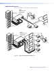
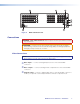
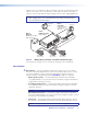
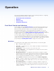
FIG_HDXP 3232 Rear Panel
I
N
P
U
T
S
1
2
3
4
5
6
7
8
9
10
11
12
13
14
15
16
O
U
T
P
U
T
S
1
2
3
4
5
6
7
8
9
10
11
12
13
14
15
16
17
18
19
20
21
22
23
24
25
26
27
28
29
30
31
32
17
18
19
20
21
22
23
24
25
26
27
28
29
30
31
32
LAN
ACT
LINK
BI-LEVEL
RESET
TRI-LEVEL
GEN-LOCK
PREVIEW
1
5
6
7
3
8
4
2
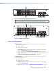
Figure 4. HDXP 3232 Rear Panel
Connections
WARNING: Risk of Electric Shock. Remove power from the system before making
any connections.
ATTENTION: Use Electrostatic discharge precautions (be electrically grounded)
when making connections. Electrostatic discharge (ESD) can damage equipment,
although you may not feel, see, or hear it.
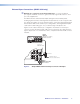
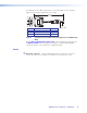
Video Connections
NOTE: The switchers do not alter the video signal in any way. The signal that is output
by the switcher is in the same format as the input signal.
a
Video inputs — Connect serial digital input sources to these female BNC
connectors.
b
Video outputs — Connect serial digital video output devices to these female BNC
connectors.
c
Preview output — Connect a digital display device to this female BNC connector to
enable you to preview a selected input when the switcher is in preview mode.