User Guide Matrix Switchers HDXP Plus Series Matrix Switchers 68-1200-01 Rev.
Safety Instructions Safety Instructions • English WARNING: This symbol, , when used on the product, is intended to alert the user of the presence of uninsulated dangerous voltage within the product’s enclosure that may present a risk of electric shock. ATTENTION: This symbol, , when used on the product, is intended to alert the user of important operating and maintenance (servicing) instructions in the literature provided with the equipment.
FCC Class A Notice This equipment has been tested and found to comply with the limits for a Class A digital device, pursuant to part 15 of the FCC rules. The Class A limits provide reasonable protection against harmful interference when the equipment is operated in a commercial environment. This equipment generates, uses, and can radiate radio frequency energy and, if not installed and used in accordance with the instruction manual, may cause harmful interference to radio communications.
Conventions Used in this Guide Notifications The following notifications are used in this guide: WARNING: A warning indicates a situation that has the potential to result in death or severe injury. ATTENTION: Attention indicates a situation that may damage or destroy the product or associated equipment. NOTE: A note draws attention to important information. TIP: A tip provides a suggestion to make working with the application easier.
Contents Introduction.................................................... 1 About this Guide.................................................. 1 About the HDXP Plus Series Matrix Switchers..... 1 Features.............................................................. 2 Application Diagrams........................................... 5 Installation...................................................... 6 Rear Panels and Cabling..................................... 6 Connections................................
Matrix Software............................................ 67 Reference Information.............................. 112 Matrix Switchers Control Program..................... 67 Downloading the Matrix Software Control Program....................................................... 67 Software Operation Via Ethernet.................... 69 Special Characters........................................ 69 Using the Software........................................ 70 Setting up the Matrix window.....................
Introduction This section gives an overview of the Extron HDXP Plus Series Matrix Switchers, describes significant features of the series, and provides application diagrams. • About this Guide • About the HDXP Plus Series Matrix Switchers • Features • Application Diagrams About this Guide This user guide contains installation, configuration, and operating information for the HDXP matrix switchers, including the HDXP 1616, HDXP 3216, and HDXP 3232 models.
The HDXP can operate in two switching modes, selectable via front panel buttons: • Matrix switching mode (mode 1): Any input may be switched to any output. • Preview selection mode (mode 2): Any single input may be selected and previewed. Each HDXP switcher has the rear panel Remote RS232/RS422 port, the front panel Config RS-232 port, and the LAN port for remote control and configuration.
• Input-output (I/O) grouping — Allows the matrix to be virtually divided into smaller sub-switchers, making installation and control easier. I/O grouping allows specific outputs, such as those designated for a specific purpose, to be grouped together. • Output reclocking — Each output has a reclocker, which detects the rate of the digital input signal stream and re-times the output signal to match it. This enables the signal to travel farther through the cable.
• Front panel security lockout (executive mode) — If a matrix switcher is installed in an open area, where operation by unauthorized personnel may be a problem, this security lockout feature can be implemented. When the front panel is locked, a special button combination, SIS command, or selection from the Windows-based control software screens is required to unlock the front panel controller before it can be operated.
Application Diagrams The following diagrams show examples of HDXP applications.
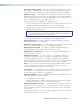
Installation This section describes the rear panels of the HDXP switchers and provides instructions for cabling and mounting. Topics include: • Rear Panels and Cabling • Connections Rear Panels and Cabling Most of the HDXP connectors are on the rear panel. Figures 2, 3, and 4 show the rear panels of the HDXP 1616, 3216, and 3232 switchers.
FIG_HDXP 3232 Rear Panel 2 13 17 21 25 29 10 14 18 22 26 30 3 7 11 15 19 23 27 4 8 12 16 20 24 28 I N P 31 U T S 32 O U T P U T S 1 5 9 13 17 21 25 29 2 6 10 14 18 22 26 30 3 7 11 15 19 23 27 31 4 8 12 16 20 24 28 32 GEN-LOCK TRI-LEVEL 9 6 BI-LEVEL 5 2 LAN 1 4 ACT LINK RESET 1 PREVIEW 6 7 3 8 Figure 4. 5 HDXP 3232 Rear Panel Connections WARNING: Risk of Electric Shock. Remove power from the system before making any connections.
External Sync Connections (HDXP 3232 only) sync connectors for bi-level and tri-level — Connect an external d External sync signal to this BNC connector to genlock the video signal in broadcast or other sync-critical applications. The HDXP switchers switch between inputs during the vertical interval period, resulting in glitch-free video switching when the input devices are also using the same sync timing. The HDXP can use an external signal to synchronize switching during the vertical interval.
Figure 6 shows a configuration in which the timing source passes through three video cameras and a video scan converter before connecting to the switcher. This type of camera can synchronize with the external timing source for video editing applications. NOTE: I/O grouping is used to set the inputs associated with each reference input. Input group 1 is associated with the tri-level signal and input group 2 is associated with the bi-level signal.
Ethernet Connection port — If desired, connect the HDXP switcher to a PC or to an Ethernet LAN f LAN via this RJ-45 connector. Use a PC to control the networked switcher with SIS ACT LINK Ethernet connection indicators — The Link and Act LEDs indicate the status of the Ethernet connection. The Link LED indicates that the switcher is properly connected to an Ethernet LAN. This LED should light steadily. The Act LED indicates transmission of data packets on the RJ-45 connector.
The cable that you use depends on your network speed. The switcher supports both 10 Mbps (10Base-T — Ethernet) and 100 Mbps (100Base-T — Fast Ethernet), half-duplex and full-duplex, Ethernet connections. • 10Base-T Ethernet requires CAT 3 UTP or STP cable at minimum. • 100Base-T Fast Ethernet requires CAT 5e UTP or STP cable at minimum.
The optional 2.5 mm cable can be used to connect the HDXP to your computer. Figure 9 shows the pin assignments for this cable. 6 feet (1.8 m) 1 6 6 5 9 9 Tip Ring I 9-pin D Connection TRS Plug Pin 2 Pin 3 Pin 5 Computer Rx line Computer Tx line Computer signal ground Tip Ring Sleeve Figure 9. Sleeve (Gnd) 2.
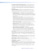
Operation This section describes the HDXP front panel controls and the procedures for configuring and operating the HDXP switchers. Topics include: • Front Panel Controls and Indicators • Operations • Troubleshooting • Configuration Worksheets Front Panel Controls and Indicators The front panel controls (see figures 10 and 11 on the next page) are grouped into two sets. The input and output buttons are on the left side of the control panel.
FIG_Front panels 1 INPUTS 1 2 3 4 5 6 7 8 9 10 11 12 13 14 15 16 17 18 19 20 21 22 23 24 25 26 27 28 29 30 31 32 CONTROL ENTER PRESET 1 2 3 4 5 6 7 8 9 10 11 12 13 14 15 16 VIEW < I/O ESC > OUTPUTS MATRIX PREVIEW HDXP PLUS SERIES SDI AND HD-SDI MATRIX SWITCHER 4 2 5 6 7 8 9 Figure 10. HDXP 1616 and HDXP 3216 Front Panel NOTE: On the HDXP 1616, which has only 16 input connectors, the input buttons in the second row (buttons 17 through 32) can be used only for preset selection.
Configuration Port (HDXP 3232 Only) port (HDXP 3232 only) — This RS-232 port is an alternative to the c Config RS232/RS422 connector on the HDXP rear panel (see Rear Panels and Cabling on page 6 for a description). This port (RS-232 only) can be used for system configuration and control via SIS commands or the Windows-based control software. For information on connecting to this port, see RS-232 and RS-422 Remote Connections on page 11.
< button — The View < button has two primary functions (❏) and eight f View secondary ( ) functions: ❏ • Places the switcher in view-only mode to display the current configuration. VIEW < NOTE: View-only mode also provides a way to mute and unmute outputs (see Muting and Unmuting Outputs) on page 33). ❏ Indicates that the HDXP is in view-Only mode. • In I/O grouping mode, selects group 3 (see I/O Grouping on page 26). • In I/O grouping mode, indicates that group 3 is selected (see I/O Grouping).
button — The Preview button has two primary functions (❏) and three i Preview secondary functions ( ): ❏ • Places the HDXP in Preview switching mode, enabling selection of one input to preview. ❏ Lights to indicate that the HDXP is in preview mode, and that only one input can be selected to be viewed. • With the Matrix button, toggles the front panel lock on or off (see Locking Out the Front Panel [Executive mode]).
3. Select an input by pressing its button. The input button you pressed lights green. NOTE: If your selected input already has outputs tied to it, the buttons of the tied outputs also light green (steadily) when you press the input button. 4. Press the button for each output that you want to tie to the selected input. • The output buttons blink green when pressed, indicating potential ties. • The Enter button also blinks green.
3. Press and release the Input 5 button. Press and release the Input 5 button. The button lights green. INPUTS 1 2 3 4 5 6 7 8 17 18 19 20 21 22 23 24 Figure 14. Selecting Input 5 4. Press and release the Output 3, Output 4, and Output 8 buttons. Press and release the Output 3, Output 4, and Output 8 buttons. The buttons blink green to indicate that the selected input will be tied to these outputs.
Example 2: Adding a tie to a set of ties In the following example, a new tie is added to the current configuration. The illustrations show the front panel indications that result from your actions. NOTE: This example assumes that you have performed example 1. 1. Press and release the Esc > button. Press the Esc > to clear all selections. CONTROL ENTER PRESET VIEW ESC The button blinks once. Figure 18. Clearing All Selections 2.
5. Press and release the Enter button. Press the Enter button to confirm the configuration change. ENTER All input and output buttons become unlit or return to background illumination. The Enter button becomes unlit or returns to background illumination. Figure 22. Confirming the Tie The configuration now is: Input 5 tied to output 1, output 3, output 4, and output 8 Input 5 tied to outputs 1, 3, 4, and 8. Input 5 1 3 4 Output 8 Figure 23.
Example 3: Removing a tie from a set of ties In the following example, an existing tie is removed from the current configuration. The steps show the front panel indications that result from your action. NOTE: This example assumes that you have performed examples 1 and 2. 1. Press and release the Esc > button. Press the Esc > to clear all selections. CONTROL ENTER PRESET VIEW ESC The button blinks once. Figure 24. Clearing All Selections 2.
5. Press and release the Enter button. Press the Enter button to confirm the configuration change. ENTER All input and output buttons become unlit or return to background illumination. The Enter button becomes unlit or returns to background illumination. Figure 28. Confirming the Tie Removal The configuration now is: Input 5 tied to output 1, output 3, and output 8 (see figure 29). Input 5 tied to outputs 1, 3, 4, and 8. Input 5 1 3 Output 8 Figure 29.
3. Press the button for the input that you want to preview. The input button lights red when pressed, and the selected input is tied to the Preview output. NOTE: Preview selection mode times out and returns to matrix mode after 30 seconds of non-use. Press and release the desired input button. The button lights red. INPUTS 1 2 3 4 5 6 7 8 17 18 19 20 21 22 23 24 Figure 31. Selecting an Input to Preview NOTE: Only one input at a time can be previewed.
2. Press and release the View < button. Press the View button to enter view-only mode. CONTROL ENTER PRESET VIEW ESC The button lights red. Figure 33. Entering View-only Mode • The View < button lights red. • The Matrix button lights green. • All of the buttons for outputs that are not tied light green. 3. Select the input or output whose ties you wish to view by pressing its input or output button. Press and release the desired input button. The button lights green.
I/O Grouping I/O grouping is a matrix switcher feature that allows you to subdivide the front panel control of the matrix into four smaller functional sub-switchers and limit tie creation from the front panel only. Inputs and outputs can be assigned to one of four groups or not assigned to any group. Inputs and outputs that are assigned to a group can be tied only to other outputs and inputs within the same group when you are creating ties on the front panel.
Suggested applications for the I/O grouping feature include: • Segregating specific video formats to prevent an input in one video format from being inadvertently applied to an output device that supports another video format (see figure 37). • Segregating input and output devices that are in separate rooms. • Isolating video from being displayed on specific output devices for operational security reasons.
3. Press and release one of the Control buttons to select a group number: • Press the Enter button to select group 1. • Press the Preset button to select group 2. • Press the View < button to select group 3. • Press the Esc > button to select group 4. In the figure 39 example, group 1 is being selected. Press the Enter button to select group 1. The button lights amber to indicate the selection. CONTROL ENTER PRESET Group# 1 2 Figure 39. VIEW ESC 3 4 Selecting an I/O Group Number 4.
Viewing I/O groups To see the groupings that have been created: 1. Press and hold the Input 1 and Output 1 buttons until all ungrouped buttons light green (approximately 3 seconds). 2. Press the Control button for the group number you want to view (Enter = group 1, Preset = group 2, View < = group 3, and Esc > = group 4). The buttons for all inputs and outputs in that group light green. 3. To view another group, repeat step 2. 4.
Saving a preset Follow these steps to save the current configuration (set of ties) as a preset. The steps show the front panel indications that result from your action. NOTE: The illustrations for this procedure show the HDXP 3216. However, the information applies to all HDXP models. 1. Press and release the Esc > button. Press the Esc > to clear all selections. CONTROL ENTER PRESET VIEW ESC The button blinks once. Figure 43. Clearing All Selections 2.
4. Press and release the Enter button. The current configuration is now stored in the selected memory location. Press the Enter button to save the preset. C O NT R O L ENTER PRESET VIEW ESC All input buttons become unlit or return to background illumination. The Enter and Preset buttons become unlit or return to background illumination. Figure 46. Press the Enter Button Recalling a preset Follow these steps to recall a preset (set of ties) to be the current configuration.
3. Press and release the input or output button for the desired preset. In figure 49, preset 1 (Input button 1) is selected. Press and release the Input 1 button. The button blinks red to indicate that this preset number is selected but not recalled. C O NT R O L ENTER PRESET VIEW ESC INPUTS 1 2 3 4 5 6 7 8 9 17 18 19 20 21 22 23 24 2 The Enter button blinks to indicate the need to recall the preset. = Blinking Button Figure 49. Select the Preset 4.
Muting and Unmuting Outputs You can mute and unmute the outputs on the HDXP using the front panel. (You can also mute and unmute them via SIS commands, the Windows-based control software, and the web pages.) NOTE: Mutings are saved to memory. When power is removed and restored, the mute settings are retained. Muting an output Follow these steps to mute an output: 1. Press the Esc > button to clear any input button indications, output button indications, or control button indications that may be on.
NOTE: The front panel times out after 30 seconds, and the View < and the blinking output buttons become unlit or return to background lighting. If you want to mute another output after a timeout, you must press the View < button again (repeat steps 2 and 3). 5. When finished muting, press and release the View < button to exit view-only mode, or wait for the front panel to time out (approximately 30 seconds). Press the View button to exit view-only mode.
Locking the Front Panel (Executive Mode) The front panel security lockout (executive mode) limits the operation of the HDXP from the front panel. When the switcher is locked, all of the front panel functions are disabled except for the view-only mode functions (see Viewing the Configuration on page 24) and front panel lock mode selection. To toggle executive mode on and off, press and hold the Matrix and Preview buttons until the two buttons blink twice (approximately 3 seconds).
Selecting the RS-232 or RS-422 Protocol and Baud Rate The HDXP switchers can support either RS-232 or RS-422 serial communication protocol, and operate at 9600, 19200, 38400, and 115200 baud rates. The settings of these variables can be viewed and changed from the front panel. NOTE: This information applies to only the rear panel Remote RS232/RS422 port. The front panel Config port is RS-232 only; RS-422 cannot be selected for it. View and configure the serial communications settings as follows: 1.
4. Press and release an input or output button to exit the serial port configuration mode. All Control and I/O buttons become unlit or return to background illumination. Press and release an input or output button. I/O C O NT R O L 5 Figure 60. ENTER PRESET VIEW ESC MATRIX PREVIEW Exiting Serial Port Configuration Mode Resetting There are several methods by which you can reset the HDXP, and some of these methods allow for four levels of resetting.
Resetting using the rear panel Reset button The rear panel has a Reset button that initiates four levels of matrix switcher resets. This button is recessed; it can be accessed with a pointed stylus, ballpoint pen, or an Extron Tweeker (a small screwdriver provided with the unit). While the switcher is running or while you are applying power to it, press and hold in the button for the number of seconds required for the desired reset level. The table below provides a summary of the rear panel reset modes.
Soft system resets The HDXPs have three soft resets available that restore various tiers of switcher settings to their default settings. • Events (mode 3) reset — This function toggles the monitoring of events on or off (if events monitoring was on, this function turns it off; if monitoring was on, the HDXP turns it off). • IP settings (mode 4) reset — The IP settings reset performs the following functions: • Enables Arp program capability. • Resets the IP address to the factory default (192.168.254.
Hard reset The hard reset function restores the HDXP to the base firmware with which it was shipped. After a hard reset, events do not automatically start, but user settings and files are restored. NOTE: The hard reset restores the factory-installed firmware. The switcher reverts to the last successfully loaded firmware the next time power is cycled off and on unless a firmware update is performed before the power cycle. To perform a hard reset: 1. If necessary, turn off power to the switcher. 2.
Configuration Worksheets Rather than trying to remember the configuration for each preset, use worksheets to record this information. Make copies of the blank worksheet at the end of this section, and use one for each preset configuration. Cross out all unused or inactive inputs and outputs. The worksheet is generic for all models of HDXP. Disregard or cross out boxes for inputs and outputs that your switcher does not have.
Worksheet Example 2: Daily Configuration Figure 65 continues from worksheet example 1 by showing the video ties that make up the configuration of preset 1. A solid ink line shows video ties.
Worksheet Example 3: Test Configuration The AV system in our fictional organization needs to be fine tuned on a regular basis. Figure 66 shows a typical test configuration, with an Extron video test generator (input 12) generating a test pattern to all monitors (outputs 1, 2, 3, 4, and 8).
HDXP Plus Series Switchers • Operation 44 18 17 Title: 19 3 19 3 20 4 20 4 21 5 21 5 22 6 22 6 23 7 23 7 25 9 25 9 Output Destinations 24 8 24 8 26 10 26 10 27 11 27 11 28 12 28 12 29 13 29 13 30 14 30 14 31 15 31 15 32 16 32 16 HDXP Configuration Worksheet Fill in the preset number and use colors, or dashes, etc. to make connecting lines. Disregard or cross out the input and output boxes that do not apply to your switcher.
Remote Configuration and Control This section describes the serial connections through which the Extron Simple Instruction Set (SIS) commands can be issued. It also lists the commands that are available for controlling and configuring the HDXP switchers.
Ethernet Port The rear panel Ethernet connector on the switcher can be connected to an Ethernet LAN or WAN. Communication between the switcher and the controlling device can be via Extron DataViewer or Telnet (a TCP socket using port 23). The Telnet port can be changed, if necessary, via SIS (for information on connecting via Telnet, see Connecting as a Telnet Client on page 115). The Ethernet connection makes SIS control of the switcher possible using a computer connected to the same LAN or WAN.
3. If the password is accepted, the switcher responds with Login User or Login Administrator. 4. If the password is not accepted, the Password prompt reappears. Number of Connections An HDXP switcher can have up to 200 simultaneous TCP connections, including all http and Telnet connections. When the connection limit is reached, the switcher accepts no new connections until some have been closed. No error message or indication is given that the connection limit has been reached.
] Login Administrator ] ] Login User ] The switcher initiates the login message when a correct administrator or user password has been entered. If the user and administrator passwords are the same, the switcher defaults to administrator privileges. Qik ] The switcher initiates the Qik message when a front panel switching or preset recall operation has occurred. Sprnn ] The switcher initiates the Spr message when a memory preset has been saved from the front panel. nn is the preset number.
Using the Command and Response Table for SIS Commands The command and response table begins on page 54. Lowercase letters are acceptable in the command field except where indicated. The table below shows the hexadecimal equivalent of each ASCII character used in the command and response table. ASCII to Hex Conversion Table Space • Figure 67. ASCII to Hexadecimal Conversion Symbols are used throughout the table to represent variables in the command and response fields.
X* = Room number (for room presets): 0 – 10. (Each room can have up to ten presets assigned.) NOTE: A room is a subset of operator-selected outputs that relate to each other. The HDXP switcher supports up to 10 rooms, each of which can consist of from 1 to 16 outputs per room.
X2^ X2& X2* X2( X3) = GMT date and time (read) in the format Www, • DD • Mmm • YYYY • HH:MM:SS Www = name of the day of the week (Mon through Sun) DD = day of the month (01 through 31) Mmm = Name of the month (Jan through Dec) YYYY = year (20nn) HH = hour (00 through 24) MM = minutes (00 through 59) SS = seconds (00 through 59) • = space = IP address (nnn.nnn.nnn.nnn). Leading zeros in each of the four fields are optional.
X4^ = Telnet port number 01 = Remote RS232/RS422 port on rear panel 02 = Config port on front panel NOTE: The port number is represented as two ASCII characters (2 bytes). For example, Port 02 is represented as 30 32 in hexadecimal. X4& X4* X4( X5) X5! X5@ X5# X5% = = = = = Baud rate (9600, 19200, 38400, or 115200) Parity (odd, even, none, mark, or space). Only the first letter is required.
X6^ = Event status field: event_type event_state event_paused error_status RcvBuff_startptr RcvBuff_endptr UsrBuff_startptr UsrBuff_endptr X6& = ASCII digits representing the numeric value of the data element read from the event buffer. (Leading zeros are suppressed.
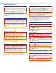
Command and Response Table for SIS Commands ASCII Command Command Response (Host to Switcher) (Switcher to Host) Additional Description Create Ties NOTES: • Commands can be entered back-to-back in a string, with no spaces between commands. Example: 1*1!02*02&003*003%4*8& • The Quick multiple tie and Tie input to all outputs commands activate all I/O switches simultaneously. • The HDXP switchers support 1-, 2-, and 3-digit numeric entries (1*1!, 02*02&, or 003*003%).
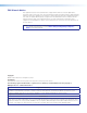
ASCII Command Command (Host to Switcher) Response (Switcher to Host) Additional Description Mute Commands (continued) Global video mute NOTE: Mute all video outputs. To mute outputs, you can also use the Input 0 command: 0 * X@ !, where input X@ is set to 0. Global video unmute View all mutes Example: HDXP 1616 NOTE: Vmt1 ] 1* B Vmt0 ] X1$ X1$...X1$n ] 0*B E VM } Unmute video for all outputs. Each X1$ response is the mute status of an output, starting from output 1.
ASCII Command Command Response (Host to Switcher) (Switcher to Host) Additional Description Save, Recall, and Directly Write Global and Room Presets (continued) Directly write global presets Example: E + X1! P X@ * X#!...X@ * X#!} Spr X1! ] Esc +27P12*5!10*09!3*2!3*8! Spr 27 ] Tie input X@ to output X# for as many ties as are desired and save all ties to preset X1!. (The ! (tie all), % (tie video), and & (tie RGB) commands can all be used.) Brackets are shown to separate ties for clarity only.
ASCII Command Command (Host to Switcher) Response Additional Description (Switcher to Host) View Ties and Presets (continued) View global video preset E X1! * X# *1VC} X@ • X@ •...• X@ • Vid ] Show preset X1! video configuration. Show the input (X@) tied to 16 sequential outputs, starting with output X#. NOTES: • For HDXP 1616 and HDXP 3216, the starting output number is 1. • To view the current video configuration, enter E 0* X# * 1VC } . Example: HDXP 3232 E 4 * 17 * 1VC } See below.
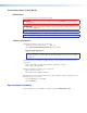
ASCII Command Command Response (Host to Switcher) (Switcher to Host) Set the output reclocker X# * X% = Rte X# * X% ] View the reclocker status X# = X% ] Additional Description Output Reclocking Example: 8 * 07 = Set the reclocking rate for output X# to X%. Show current reclocking rate X% for output X#. Rte X# * X% ] Verbose mode 2 or 3 Rte 08 * 07 ] The reclocking rate for output 8 is 1485. I/O Grouping NOTE: All input and output positions must contain a group number or 0.
ASCII Command Command Response Additional Description (Host to Switcher) (Switcher to Host) E X*,X#,...X#n MR } Mpr X*,X#,...X#n ] Assign outputs X# through X#n to room X*. E X* MR } Name,X#,...X#n ] Show outputs X# through X#n assigned to room X*. E 3MR } Class1,01,02,08,09 ] Rooms Write room outputs NOTES: • The maximum number of outputs per room is 16. • The maximum number of rooms is 10. • An output can be assigned to only one room.
Command ASCII Command Response Additional Description (Host to Switcher) (Switcher to Host) Lock all front panel functions 1X Exe1 ] Enable lock mode 1. Unlock all front panel functions View lock status 0X X Exe0 ] X( ] Enable lock mode 0. View lock mode status X(.
ASCII Command Command Response (Host to Switcher) (Switcher to Host) Additional Description Information Requests (continued) Request part number 60-nnn-01] Show the HDXP part number: HDXP 3232 = 60-797-01 HDXP 3216 = 60-790-01 HDXP 1616 = 60-876-01 Query controller firmware Q X1( ] View firmware version X1( to version the second decimal place. The factory-installed controller Example: Q 1.23 ] firmware version is 1.23.
Command ASCII Command (Host to Switcher) Response (Switcher to Host) Additional Description Information Requests (continued) View File Directory Commands (continued) View file directory web browser E DF } Var file = new array (); File [1] = ‘filename1,date1,filesize1’; File [2] = ‘filename2,date2,filesize2’; File [3] = ‘filename3,date3,filesize3’; ...
Command ASCII Command (Host to Switcher) Response (Switcher to Host) Additional Description IP Setup Commands (continued) Set DHCP on or off Read DHCP status Set IP address Read IP address Read hardware (MAC) address E X4% DH } E DH } E CI X2& CI } E CI } E CH } Idh X4% ] Set subnet mask E X5* CS } Ips X5* ] Read subnet mask E CS} X5* ] Set gateway IP address E X5( CG } Ipg X5( ] Read gateway IP address Set administrator password E CG } E X3) CA } X5( ] Ipa • X3) ] Read administrator pas
Command ASCII Command (Host to Switcher) Response (Switcher to Host) Additional Description IP Setup Commands (continued) Bidirectional Serial Port (continued) Configure flow control24 E X4^ * X5@,X5# CF } Cpn X4^ • Cfl X5@,X5# ] View flow control E X4^ CF } X5@,X5# ] Configure receive timeout24 E X4^ * X1& * X1* * X6( * X6* CE } Cpn X4^ • Cce X1&,X1* ] View receive timeout E X4^ CE } X1&,X1*,X6(,X6* ] Send data string (web encoding only) E X4^ * X1& * X1* * X5^ RS } X5% Response to comman
Command ASCII Command (Host to Switcher) Response (Switcher to Host) Additional Description IP Setup Commands (continued) E-mail commands Read connection security level E CK } X3! ] Set mail server IP address and domain name E X2&,X3* CM } Ipm X2&,X3* ] Read mail server IP address, domain name, and password E CM } X2&,X3*,X3) ] Set e-mail recipient E X4!,X3# CR } Ipr X3# ] Example: View e-mail recipient Set e-mail events for recipient Example: View security level X3! of the current conn
Command ASCII Command (Host to Switcher) Response (Switcher to Host) Additional Description IP Setup Commands (continued) E-mail Commands (continued) Read e-mail events for recipient Example: HDXP 1616 E X4! EM } X4@,X4$ ] E 72EM } See below. Notify failed and fixed E-mail input 8 status View notification status X4$ for e-mail account X4!.
Matrix Software This section describes the procedures for using the software products provided for the HDXP switchers. • Matrix Software Control Program • Creating Button Labels The following software programs accompany the HDXP 3232, 3216, and 1616 switchers: • The Windows-based Extron Matrix Switcher Control Program, which communicates with the switcher via the RS232/RS422 port and the Ethernet port, provides an easy way to set up ties and sets of ties.
FIG_SW download links Figure 68. Software Links on the Download Page 3. On the next page, click the M link of the alphabet at the center or the bottom of the page. 4. Scroll to locate the Matrix Switchers software, then click the Download link to the right. Figure 69. 5. Download Link for the Matrix Switcher Control Program On the next screen, fill in the requested information, then click the Download MATRIX_SW_vnxn.exe button. 6.
7. If a second security prompt window opens, click Run again to start the installation process. 8. Follow the instructions on the InstallShield Wizard screens to complete the software program installation. By default, the software installation creates a C:\Program Files\Extron\Matrix Software or C:\Program Files (x86)\Extron\Matrix Software directory and places two files (MATRIX Switcher+ Control Program [MTRX.exe] and MATRIX Switcher+ Help [MTRX.hlp]) in it.
Using the Software Many items in the Windows-based Matrix Switcher Control Program are also accessible via front panel controls (see the Operation section beginning on page 13), under SIS control (see the Remote Configuration and Control section beginning on page 45), and via the web pages (see the HTML Configuration and Control section beginning on page 96). The Matrix Switcher Control Program help file provides information on settings and on how to use the control program itself. 1.
c. Click OK and proceed to step 4. Figure 71. Baud Rate Pop-up List • If you selected IP [LAN], click OK and proceed to step 3. • If you selected Emulate, click OK and see Using Emulation Mode on page 89. 3. If you selected IP [LAN] in step 2, the IP Connection window opens. Figure 72. Address and Password Entry for IP Connection a. Check the Extron IP Address field in the IP Connection window. The field displays the last Extron IP address entered.
4. The Extron Matrix Switcher Control Program window opens. The window displays the current configuration of the attached matrix, with numbered boxes representing the video inputs and outputs. NOTE: Figures 73 and 74 show the HDXP 3232, which has 32 inputs and 32 outputs. The window for the HDXP 3216 has 32 input boxes and 16 output boxes, while the HDXP 1616 window has 16 input boxes and 16 output boxes. Figure 73. Extron Matrix Switcher Control Program Window (No Ties) Figure 74.
Setting up the Matrix window On the Matrix window, the inputs and outputs are represented by boxes. You can make the control program easier to use by assigning device icons that represent your connected devices to each input and output box. 1. Click on an input or an output box. The Input Devices or Output Devices window opens, containing icons representing devices that can be connected to a switcher. Figure 75. Input Devices and Output Devices Icon Windows 2.
Managing Ties On the Matrix window, you can create, dissolve, and view input-to-output ties as follows: • To create a tie, click and drag from an input box to an output box. • If Hold/Verify Changes has been selected from the Preferences menu: A broken line appears, connecting the two boxes. (If you want to undo the preliminary tie at this point, click the Cancel button. The broken line disappears.) Click Take to confirm the tie. The broken line becomes solid.
IP Setup The IP Settings/Options window (see figure 78) lets you view and, if connected via the RS-232 or RS-422 link or if you are logged on via the Ethernet port as an administrator, editing settings unique to the Ethernet interface. None of the fields on this screen can be edited while you are logged on as a user. To display the IP Settings/Options window, select IP Options from the Tools drop-down menu. Figure 78.
Setting the matrix IP address The Matrix IP Address field contains the IP address of the connected matrix switcher. This value is encoded in the flash memory on the switcher. Valid IP addresses consist of four 1-, 2-, or 3-digit numeric subfields separated by dots (periods). Each field can be numbered from 000 through 255. Leading zeros, up to 3 digits total per field, are optional. Values of 256 and above are invalid. The default address is 192.168.254.
Setting the gateway IP address The Gateway IP Address field identifies the address of the gateway to the mail server to be used if the HDXP switcher and the mail server are not on the same subnet. Valid IP addresses consist of four 1-, 2-, or 3-digit numeric subfields separated by dots (periods). Each field can be numbered from 000 through 255. Leading zeros, up to 3 digits total per field, are optional. Values of 256 and above are invalid. Edit this field as follows: 1.
Setting the date The Date field displays the current date in the Greenwich Mean Time zone. If necessary, adjust the date as follows: 1. Click in the Date field. A date editing field appears, displaying the date in the format (M)M/(D)D/YYYY, as shown at right. Leading zeros are not used. The graphic cursor becomes a text cursor in the date editing field. 2. Edit the field as desired to set the proper date. Leading zeros are optional. 3.
Setting the administrator password The Administrator Password field displays the password required to log on to the HDXP switcher via the Ethernet port with all administrator rights and privileges. Passwords are case sensitive and are limited to 12 uppercase and lowercase alphanumeric characters. While you are logged on as a user, this field is masked with asterisks (************) as a security measure.
Setting the mail server IP address The IP Address field in the Mail Server section displays the IP address of the mail server that handles the e-mail for the facility in which the HDXP switcher is installed. Valid IP addresses consist of four 1-, 2-, or 3-digit numeric subfields separated by dots (periods). Each field can be numbered from 000 through 255. Leading zeros, up to 3 digits total per field, are optional. Values of 256 and above are invalid. Edit this field as follows: 1.
3. Press the key on the keyboard or click in another field to exit the e-mail addressee field. 4. Use the check boxes associated with each addressee to select the options about which the addressee will be e-mailed: missing inputs or power supply. 5. When you select either a radio button or a check box for an addressee, the floating box that contains the input numbers is displayed on the Input Settings/Options screen. Select the inputs that need monitoring by clicking on their numbers in this box.
2. Start the Matrix Switcher Control Program and connect to the HDXP switcher (see steps 1 through 4 under Using the Software on page 70 for the procedure). NOTE: The Ethernet connection is much faster than the RS-232 or RS-422 connection. Extron recommends using the Ethernet connection rather than the serial port for firmware uploads. 3. From the Tools menu, select Update Firmware.... The Select files to Upload to Extron Server window opens. 4. Navigate to the folder where you saved the firmware file.
Uploading HTML Files You can create customized HTML pages for the HDXP to display. The HTML Files List window (shown below) provides a way to view the contents of the HDXP file system and to upload custom HTML pages to the switcher. Figure 82. HTML Files List Window Upload HTML pages as follows: NOTES: • The files listed in figure 82 are shown for example only and may not be present on your switcher. • The HTML Files List window is for inserting your own HTML pages.
Windows Buttons, Menus, and Trash Can The buttons, drop-down menus, and trash can icon on the right side of the program window perform the following functions: • Power — This button is unavailable for HDXP switchers, because the HDXP cannot be powered on and off via software. • Executive mode — Allows you to lock out front panel operations, except for the view-only mode functions. • Room menu — Displays a list of up to 10 rooms. From this list you can select a room to display in the window.
Tools menu The Tools menu contains the following options. (Grayed out options are unavailable on your switcher.) • Assign Device Icons — Displays the complete set of input and output device icons. You can drag any of these icons to the input and output boxes. • Edit Device Palette — Allows you to add your own device icon graphics. • Mute-Output settings — Displays the Channel Mute Settings window.
• Hardware status — Opens the HDXP Plus System Status window, which provides an overall view of the status of the matrix switcher, including the primary and secondary power supply status and the individual voltages, the internal temperature, the Remote RS232/RS422 port configuration, the number of IP connections, and the installed and updated firmware status (see figure 84). Figure 84.
• I/O Group settings — Opens the Input/Output Groups window, which allows you to establish input and output groups. Drag two or more of the small boxes representing inputs and outputs to one of the input or output Group boxes. Repeat as desired. Click Take to establish the groups. Figure 85. • Input/Output Groups Window Room configuration — Allows you to assign outputs to rooms or delete outputs from rooms. Drag one or more of the small boxes representing outputs to one of the Room boxes.
• Ties as Lines — Displays ties as lines. Figure 86. • Ties Shown as Lines Ties as Crosspoints — Displays ties as a matrix of inputs and outputs. Ties that have been made are indicated as amber boxes. Ties that will take effect when you click the Take button are indicated by a plus sign (+) in the crosspoint box. Ties that will be broken when you click the Take button are indicated by a minus sign (–). Figure 87.
• Frequency-read options — Provides a submenu that allows you to set the input signal detection (DSVP) feature to do one of the following: • Automatically refresh the display (set this option to Automatically every 10 seconds). • Sample the sync and update the display whenever you make a configuration change (set this option to On Demand or by Refresh). • Never sample and display the sync or no sync status (set this option to None).
3. From the Initialize Emulated Matrix Settings From window, select an emulation file (.mtx extension), and click Open. Figure 88. Selecting an Emulation File NOTE: Selecting the Demo.mtx file provides a sample of a completed matrix setup. Selecting the New.ini file or clicking Cancel provides a blank setup to get you started. 4. On the Save Emulated Matrix Settings window, enter a file name under which you want to save any changes to the file, and click Save. Figure 89.
5. On the Emulation Configuration window, select the number of video boards that your model has and the matrix switcher model you are configuring, and click OK. Figure 90. Emulation Configuration Window 6. Continue using the program as described in Using the Software on page 70.
Creating Button Labels The button caps are pre-labeled for your convenience by default. However, you can replace the labels of the input and output buttons with the included additional printed button labels or with labels that you create and print yourself. You can temporarily remove the numbered translucent covers on the input and output buttons to insert different labels behind the covers. Page 95 contains blank button labels.
1. To run the label creation program, double-click on the Button Label Generator icon (shown at right) in the Extron Electronics group or folder. The Button Label Generator window opens. Figure 92. Button Label Generator Window 2. From the Systems menu, select HDXP Plus 1616/1632 or HDXP Plus 3232 for the layout of your model (although you can select any option from this menu).
Replacing Button Labels The button assembly consists of a clear lens cap, the button label, and a white diffuser. Remove the button assembly from the HDXP as follows: 1. Remove the button assembly by inserting a small, flat-bladed screwdriver, such as an Extron Tweeker, between the button base and the diffuser to gently pry the button assembly off the button plunger, as shown in figure 93. 2.
Blank Button Labels HDXP Plus Series Switchers • Matrix Software 95
HTML Configuration and Control This section provides procedures for accessing and using the HDXP embedded web pages. Topics include: • Accessing the Web Pages • System Status Page • System Settings Page • Using the File Management Page • Set and View Ties Page NOTE: If your Ethernet connection to the matrix switcher is unstable, try turning off the proxy server in your web browser.
5. Press the keyboard key. The switcher checks to see if it is password protected. • If the switcher is not password protected, the System Status web page is displayed. • If the HDXP is password protected, the network password dialog box is displayed. Figure 94. Example of a Network Password Dialog Box 6. In the Password field, enter the appropriate administrator or user password.
System Status Page The System Status page (see figure 95) provides an overall view of the status of the matrix switcher, including individual voltages and serial port status (if applicable). The System Status page is the default page that the switcher downloads when you connect to the switcher. Access the System Status page from other pages by clicking the Status tab. Figure 95.
System Settings Page The HDXP switcher displays the System Settings page (shown in figure 97) when you click the Configuration tab. The screen consists of fields in which you can view and edit IP administration and system settings. The Email Settings and Passwords pages can be accessed by clicking the appropriate link on the sidebar menu (see Setting an IP Address on page 113 for basic information about IP addresses and subnetting). Figure 97.
IP Settings Fields The IP Settings fields provide a location for viewing and editing settings unique to the Ethernet interface. After editing any of the settings on this page, click the Submit button at the bottom of the IP Settings section. Unit Name field The Unit Name field contains the name used as the “from” information when the HDXP e-mails notification of its failed or repaired status. You can change this name field to any valid name, up to 24 alphanumeric characters.
Date/Time Settings Fields The Date/Time Settings section provides a location for viewing and setting the time functions. Figure 98. Date/Time Settings Section Change the date and time settings as follows: 1. Click the drop-down menu for the desired variable. The adjustable variables are month, day, year, hours, minutes, am or pm, and (time) zone (the Month drop-down menu is displayed in figure 98). 2. Click and drag the slider or click the Scroll Up until the desired variable is visible.
Passwords Page Access the Passwords page by clicking the Passwords link on the sidebar menu on System Settings page. Figure 99. Passwords Page The fields on the Passwords page are for entering and verifying administrator and user passwords. Passwords are case sensitive and are limited to 12 upper- and lowercase alphanumeric characters. Each password must be entered twice — once in the Password field and then again in the Re-enter Password field to the right.
Email Settings Page Access the Email Settings page by clicking the Email Settings link on the sidebar menu on the System Configuration page. The Email Settings page has fields for setting up the HDXP e-mail notification capabilities. For the e-mail settings and for each row of the e-mail notification settings, click the Edit button at the right of the field to make the field available for editing. The button changes to Save.
SMTP Authorization Required fields Selecting the SMTP Authorization Required check box sets the HDXP to require SMTP authorization before accepting any e-mail. To set up this authorization requirement, follow these steps: 1. To enable the SMTP authorization fields, click the Edit button at the right of the Mail IP Address field. The Edit button changes to Save. 2. Select the SMTP Authorization Required check box, located below the Domain Name field.
Firmware Upgrade Page The Firmware Upgrade page provides a way to replace the firmware that is coded on the HDXP control board without needing to take the switcher out of service. Access the Firmware Upgrade page by clicking the Firmware Upgrade link on the System Settings page. Figure 102. Firmware Upgrade Page NOTE: The Firmware Upgrade page is only for replacing the firmware that controls all switcher operation. To insert your own HTML pages, see Using the File Management Page on page 107.
6. Navigate to the folder where you saved the firmware upgrade file. Select the file. Figure 103. Open Window with an HDXP Firmware File Selected NOTES: • Valid firmware files must have the file extension .S19. A file with any other extension is not a firmware upgrade. • The original factory-installed firmware is permanently available on the HDXP switcher. If the attempted firmware upload fails for any reason, the HDXP reverts to the factory-installed firmware. 7. Click Open. 8.
Using the File Management Page To delete files (such as HTML pages) from the switcher or to upload your own files to the switcher, click the File Management tab. The switcher displays the File Management HTML page. Figure 104. File Management Page NOTE: The files listed in figure 104 are shown for example only and may not be present on your switcher. Uploading Files Files to be uploaded to the HDXP must contain only valid alphanumeric characters and underscores.
Adding a Directory To add a directory or folder to the HDXP file system, follow these steps: 1. Enter the directory name in the Dir: field, following the slash (/). 2. Click the Add button. 3. With the directory name displayed, perform the uploading files procedure described in the previous section to add a file to the directory. The directory name appears at the top of the Files column, preceded by a slash.
Set and View Ties Page You can create ties on the Set and View Ties page (see figure 105). Access the Set and View Ties page by selecting the Control tab. Figure 105. Set and View Ties Page The Set and View Ties page consists of a matrix of input (rows) and output (columns) selection buttons. Creating a Tie Select and switch an input as follows: 1. Move the mouse over the matrix of input and output selection buttons.
Output Settings Page The Output Settings page allows you to mute or unmute and to change the reclocker rate of the outputs on your unit. Figure 106. Output Settings Page Muting and unmuting the output To mute or unmute an output, do the following: 1. To select an individual output to mute or unmute, select an output number from the Output drop-down menu. 2. Select or clear the Mute/Un-Mute check box. The word Muted appears in red next to the output selection menu.
Global Presets Page You can save and recall global presets from the Global Presets page. Access the Global Presets page by clicking the Global Presets link on the left panel of the Control page. Figure 107. Global Presets Page Saving a preset Save the current configuration (configuration 0) as a preset as follows: 1. Click the Save Preset button. It changes to Select Preset.... 2. Select the desired preset by clicking one of the preset buttons.
Reference Information This section provides reference information on the HDXP Plus products. Topics include: • Mounting the Switcher • Setting an IP Address Mounting the Switcher The HDXP matrix switchers are housed in rack-mountable metal enclosures with mounting flanges for standard 19-inch racks. If desired, rack mount the HDXP switcher as follows: 1. Insert the switcher into the rack, aligning the holes in the mounting flanges with those in the rack. 2.
Setting an IP Address What is an IP Address? An IP address is a 32-bit binary number that is used to identify each device on an Ethernet network. This number is usually represented by four decimal numbers (called “octets”), each in the range of 0 through 255 and separated by dots; for example, 198.123.34.240. This is called “dotted decimal notation.
The following is an example of an invalid Class C addressing scheme: Device IP Address Matrix Switcher Control Software computer 208.132.180.41 HDXP Plus switcher 192.157.180.42 NOTE: The above addresses are invalid because the network identifier for each address is not the same even though each IP address is unique. You can perform a test from your computer to check that a device at a particular address is responding correctly or to determine its address (see Pinging for the IP Address).
4. At the command prompt, enter ping IP address. The computer returns a display similar to figure 109. The line Pinging ... reports the actual numeric IP address, regardless of whether you entered the actual numeric IP address or an alias name. C:\>ping 192.168.254.254 Pinging 192.168.254.254 with 32 bytes of data: Reply Reply Reply Reply from from from from 192.168.254.254: 192.168.254.254: 192.168.254.254: 192.168.254.
Operating using Telnet This guide does not detail all of the operations and functionality of Telnet. However, some basic level of understanding is necessary for operating the HDXP switcher via Telnet. Connecting to the HDXP (Open command) You connect to the HDXP Plus switcher using the Open command. After your computer is connected to the switcher, you can enter the SIS commands the same as you would if you were using the RS-232 or RS-422 link. 1. At the Telnet prompt, enter open IP address.
Setting carriage return-line feed Unless commanded otherwise, Telnet transmits a line feed character only (no carriage return) to the connected switcher when you press the key. This is the correct setting for SIS communication with the switcher. The Telnet set crlf command forces Telnet to transmit carriage return and line feed characters when is pressed; however, if crlf is set, the SIS link with the switcher does not function properly.
Subnet masks and octets The subnet mask (see figure 112) is used to determine whether the local and remote devices are on the same subnet or different subnets. The subnet mask consists of four numeric octets separated by dots. Each octet can be numbered from 000 through 255. Leading zeros, up to three digits total per octet, are optional. Each octet typically contains either 255 or 0.
Extron Warranty Extron Electronics warrants this product against defects in materials and workmanship for a period of three years from the date of purchase.