User Guide DVI and HDMI® HDMI DA2 Distribution Amplifier 68-1844-01 Rev.
Safety Instructions • English This symbol is intended to alert the user of important operating and maintenance (servicing) instructions in the literature provided with the equipment. This symbol is intended to alert the user of the presence of uninsulated dangerous voltage within the product enclosure that may present a risk of electric shock. Warning Power sources • This equipment should be operated only from the power source indicated on the product.
FCC Class A Notice This equipment has been tested and found to comply with the limits for a Class A digital device, pursuant to part 15 of the FCC rules. The Class A limits provide reasonable protection against harmful interference when the equipment is operated in a commercial environment. This equipment generates, uses, and can radiate radio frequency energy and, if not installed and used in accordance with the instruction manual, may cause harmful interference to radio communications.
Conventions Used in this Guide Notifications the following are used: DANGER: Danger indicates a situation that will result in death or severe injury. WARNING: CAUTION: A warning indicates a situation that has the potential to result in death or severe injury. A caution indicates a situation that may result in minor injury. ATTENTION: Attention indicates a situation that may damage or destroy the product or associated equipment. NOTE: A note draws attention to important information.
Contents Introduction............................................. 1 Reference Information........................... 14 About the HDMI DA2....................................... 1 HDMI DA2 Features.......................................... 1 HDMI DA2 Application Diagram........................ 2 HDMI DA2 Specifications................................ 14 Accessories and Part Numbers......................... 15 Included Parts............................................. 15 Optional Parts..................
HDMI DA2 • Contents vi
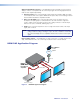
Introduction This guide describes the function, installation, and operation of the Extron HDMI DA2 distribution amplifier. Unless otherwise stated, the terms “distribution amplifier” or “DA” refer to the HDMI DA2. This section provides the following information: zz About the HDMI DA2 zz HDMI DA2 Features zz HDMI DA2 Application Diagram About the HDMI DA2 The Extron HDMI DA2 distribution amplifier distributes one HDMI input signal to two outputs simultaneously.
Output Compatibility Correction — The HDMI DA2 monitors the EDID of each connected display to ensure it is compatible with the current input signal. The following adjustments are made for each output independently: zz Interface format: If the connected display is DVI and the input signal is HDMI, the signal is reformatted to DVI. If the output is HDMI and the input is DVI, no reformatting is needed because HDMI is backwards compatible with DVI.
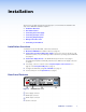
Installation This section of the guide describes the following topics concerned with the installation and setup of the HDMI DA2 distribution amplifier. zz Installation Overview zz Rear Panel Features zz Connecting the Power Supply zz Connecting the Input Source zz Connecting Output Displays zz Wiring for RS-232 Control zz Connecting to the USB Port Installation Overview To install and set up the HDMI DA2, follow these instructions: 1. Mount the HDMI DA2 in a suitable location (see page 27).
Connecting the Power Supply Connect the provided 12 VDC, 1 A power supply to the HDMI DA2 by following these instructions: ATTENTION: • This product is intended to be supplied by a Listed Power Unit marked “Class 2” or “LPS,” rated 12 VDC, maximum 1.0 A. Always use a power supply supplied or specified by Extron. Use of an unauthorized power supply voids all regulatory compliance certification and may cause damage to the supply and the end product.
Connecting the Input Source Use a HDMI cable to connect the input source to the female HDMI socket on the rear panel (b in figure 2). The connectors are fully HDCP compliant. With cables up to 25 feet (7.6 m) they support resolutions of up to 1080p @ 60 Hz with 12-bit color. With cables up to 50 feet (15.2 m) they support 1080p or 1920x1200 @ 60 Hz with 8-bit color. Follow these instructions to secure the input and output HDMI connectors to the HDMI DA2 with the LockIt™ HDMI lacing bracket provided: 1.
Wiring for RS-232 Control (Optional) RS-232 communication between the HDMI DA2 and a host PC can be used to update firmware or configure the distribution amplifier using SIS commands (see “Command and Response Table for SIS Commands“ on page 19). The computer connects to either the rear panel 3-pole RS-232 port (d in figure 2 on page 3) or the front panel USB port (b in figure 7 on page 9) of the distribution amplifier.
Connecting to the USB Port The mini Type B USB port is located on the HDMI DA2 front panel (b in figure 7 on page 9). It can be used to connect the distribution amplifier to a host computer to update firmware or for configuration using SIS commands. 1. Connect a USB A to mini B cable between the USB Config port on the front panel of the HDMI DA2 and the USB port of the PC.
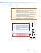
zz Select Yes, this time only to connect the PC to Windows Update only this one time. zz Select Yes, now, and every time I connect a device to automatically connect to Windows Update every time the HDMI DA2 connects to this USB port. zz Select No, not this time if you do not want to connect to Windows Update (for example, if the driver is already on the PC). 3. Click Next. The next screen of the Wizard opens: Figure 6. Installing the Software Automatically 4.
Operation This section of the manual provides information on: zz HDMI DA2 Front Panel Features zz EDID Minder HDMI DA2 Front Panel Features c CONFIG OUTPUTS 1 2 INPUT SIGNAL EDID HDCP HDMI DA2 a Figure 7. a b c d e b HDMI DA2 Front Panel d e Power status LED USB Config port Signal LEDs HDCP LEDs EDID LED Power Status LED The power status LED lights green when power is applied to the unit. USB Config Port The USB Config port is used for SIS configuration, monitoring, and firmware updates.
Signal Status LEDs Input Signal LED The input signal LED lights green when a TMDS signal is detected on the HDMI input. If the source requires HDCP encryption, this LED may light only after the HDCP has been authenticated. Output Signal LEDs There are two output signal LEDs, one for output 1 and the other for output 2. The LEDs light green when a TMDS signal is being transmitted to a sink device on the corresponding HDMI output.
EDID Minder EDID Minder ensures that the connected source sees the EDID of a display, even if a display is not connected. Depending on the EDID mode selected (by SIS command), the EDID of a connected display can be stored automatically, or the user can manually select from the table of factory loaded EDID files. This EDID is stored on an EEPROM located at the HDMI input. By default, the HDMI DA2 is configured to store EDID from the display connected to output 1 automatically.
HDMI DA2 • Operation 12 1024x768 1280x720 10 11 2048x1080 800x600 1024x768 1280x768 1280x800 1280x1024 24 25 26 27 28 29 60 Hz 60 Hz 60 Hz 60 Hz 60 Hz 60 Hz 60 Hz 60 Hz 60 Hz 60 Hz 60 Hz 60 Hz 60 Hz 60 Hz 60 Hz 60 Hz 60 Hz 60 Hz 60 Hz 60 Hz 60 Hz Refresh Rate PC PC PC PC PC PC PC PC PC PC PC PC PC PC PC PC PC PC PC PC PC Rate Type 1 1,2,3 HDMI HDMI HDMI HDMI HDMI DVI DVI DVI DVI DVI DVI DVI DVI DVI DVI DVI DVI DVI DVI DVI DV
Footnotes for the EDID table (see page 12) The following footnotes apply to the EDID table on the previous page: Rate Type 1 zz PC: These are primarily VESA standard computer rates, based on the most commonly used native resolutions. They are designed to be used with computer sources. zz HDTV: These are video rates standardized by SMPTE and CEA. They are designed to be used with video and computer sources. Video Format 2 zz DVI: These are 128-byte EDID files, which specify a DVI sink.
Reference Information This section provides information about HDMI DA2 Specifications Accessories and Part Numbers HDMI DA2 Specifications NOTE: *Appropriate HDMI to DVI-D cables or adapters are required for DVI signal input/output. Video Maximum data rate ��������������������� Maximum pixel clock ������������������� Resolution range ������������������������� Formats ��������������������������������������� Standards ������������������������������������ Up to 6.75 Gbps (2.
General Power ����������������������������������������� Input ������������������������������������� Output ���������������������������������� Power consumption Device ����������������������������������� Device and power supply ������� Temperature/humidity ������������������ External 100-240 VAC, 50-60 Hz 12 VDC, 1 A, 12 watts 4.0 watts 5.
Optional Parts Description Part Number RSF 123: 3.5 inches deep, 1U rack shelf kit 60-190-20 RSB 123: 3.5 inches deep, 1U basic rack shelf 60-604-21 RSU 126: 6 inches deep, 1U rack shelf kit 60-190-10 RSB 126: 6 inches deep, 1U basic rack shelf 60-604-11 RSU 129: 9.5 inches deep, 1U rack shelf kit 60-190-01 RSB 129: 9.5 inches deep, 1U basic rack shelf 60-604-02 UC 50' (50 feet / 15.2 m) 26-518-01 UC 100' (100 feet / 30.5 m) 26-518-02 9DM-9DM232 12' (12 feet / 3.
SIS Commands This section provides information about the SIS commands that are used to configure the HDMI DA2. The following topics are discussed: zz Introduction to SIS zz Symbols Used in this Guide zz Command and Response Table for SIS Commands Introduction to SIS The HDMI DA2 accepts SIS commands from a host device such as a computer running the Extron DataViewer utility or other control system.
Symbols Used in this Guide When programming in the field, certain characters are most conveniently represented by their hexadecimal rather than their ASCII values. The table below shows the hexadecimal equivalent of each ASCII character: ASCII to HEX Conversion Table Space . Table 2.
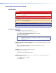
Command and Response Table for SIS Commands Command ASCII Command (host to unit) Response (unit to host) Additional Description Video mute single output X!*X@B VmtX!*X@] Video mute output X! (1 or 2) Video mute all outputs X@B VmtX@] Video mute all outputs Query Video mute status B VmtX@•X@] output 1 status, output 2 status Video Mute X@ = 0 (mute disabled) or 1 (mute enabled) Audio Mute VmtX!*X@] Video mute output X! (1 or 2)only Audio mute all outputs X!*X@Z X@Z VmtX@] Video mute a
Command ASCII Command (host to unit) Response (unit to host) Request part number N 60-997-01] Query firmware version Q X&] Additional Description Other X& = Firmware build (2 decimal places) Reset EZXXX} Zpx] HDMI DA2 • SIS Commands 20
Updating Firmware Updates to the HDMI DA2 firmware are released periodically on the Extron website. You can find which version is currently loaded on your DA using SIS commands. Compare this with the latest release on the Extron website and decide whether to update your firmware. TIP: Read the Release Notes provided on the website with the latest firmware to determine whether you need the latest version.
Downloading HDMI DA2 Firmware To obtain the latest version of firmware for your HDMI DA2: 1. Visit the Extron website (www.extron.com), click the Download link at the top of the page, then click the Firmware link on the left sidebar menu. Figure 9. Firmware Link on the Download Tab 2. On the Download Center screen, locate the section for the HDMI DA2 firmware 3. (Optional) click Release Notes. These notes show the issues that have been addressed by the latest update.
Loading the Firmware to the HDMI DA2 To load a new version of firmware to the switcher using Firmware Loader, connect your computer serial port to the first three pins of the switcher Remote port (see “Wiring for RS‑232 Control” on page 6 for information on connecting to the serial port). 1. If you have not already done so, download and install the Firmware Loader executable installer file to your computer (see “Downloading and Installing Firmware Loader” on the previous page). 2.
9. On the Open window, navigate to the new firmware file, which has an S19 extension, and double-click it. Figure 11. Open Window for Firmware File Selection ATTENTION: Valid firmware files must have the file extension S19. A file with any other extension is not a firmware upgrade for this product and could cause the HDMI DA2 to stop functioning. NOTES: • The original factory-installed firmware is permanently available on the HDMI DA2.
On the Add Device window, the path to the new firmware file is displayed in the Path field. Figure 12. Path to the New Firmware File on the Add Device Window 10. If this is the only device to which you are uploading firmware, click Add. The HDMI DA2 information is added to the Devices section of the Firmware Loader window and the Add Device window closes. If you will be uploading the firmware to multiple HDMI DA2 units that are connected to your computer, do the following: a. Click Add Next.
Figure 13. Firmware Loader Screen with a HDMI DA2 Added 11. If you want to remove a device from the Devices section, do the following: 1. Click on the names of the devices to be deleted, to highlight them. 2. Select Remove Selected Device(s) from the Edit menu. 3. On the Remove Device(s) window, select or deselect any devices on the list as desired, then click Remove. To remove all devices, select Remove All Devices from the Edit menu. 12. Click Begin.
Mounting Desktop Placement Attach the four provided rubber feet to the bottom of the HDMI DA2 and place it in any convenient location. Rack Mounting UL Guidelines for Rack Mounting The following Underwriters Laboratories (UL) guidelines are relevant to the safe installation of these products in a rack: 1.
Extron Warranty Extron Electronics warrants this product against defects in materials and workmanship for a period of three years from the date of purchase.