User Guide Signal Processors GSS 100 Graphic Still Store 68-974-01 Rev.
Safety Instructions • English Warning This symbol is intended to alert the user of important operating and maintenance (servicing) instructions in the literature provided with the equipment. Power sources • This equipment should be operated only from the power source indicated on the product. This equipment is intended to be used with a main power system with a grounded (neutral) conductor. The third (grounding) pin is a safety feature, do not attempt to bypass or disable it.
FCC Class A Notice This equipment has been tested and found to comply with the limits for a Class A digital device, pursuant to part 15 of the FCC Rules. Operation is subject to the following two conditions: 1. This device may not cause harmful interference. 2. This device must accept any interference received, including interference that may cause undesired operation.
Conventions Used in this Guide In this user guide, the following are used: NOTE: A note draws attention to important information. TIP: A tip provides a suggestion to make working with the application easier. CAUTION: WARNING: A caution indicates a potential hazard to equipment or data. A warning warns of things or actions that might cause injury, death, or other severe consequences.
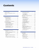
Contents Introduction............................................. 1 HTML Control and IPL File Manager...... 28 About this Guide.............................................. 1 About the GSS 100 Graphic Still Store.............. 1 Features............................................................ 2 Configuring the Hardware.............................. 29 PC Configuration........................................ 29 Initial Startup.............................................. 29 GSS Configuration.......
GSS 100 Graphic Still Store • Contents ii
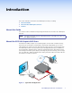
Introduction This section introduces the Extron® GSS 100 Graphic Still Store, including: zz About this Guide zz About the GSS 100 Graphic Still Store zz Features About this Guide This manual contains installation and operating information for the Extron GSS 100 Graphic Still Store. NOTE: Throughout this guide, the unit is identified as either "GSS 100," the “GSS,” or the “graphic still store.
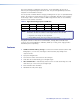
User-selected images, including the test patterns, can be uploaded to the GSS via its Ethernet port using HTML pages built into the GSS. The pass-through RGB input and the output are via female BNC connectors. The GSS provides 16 MB of RAM for storage, providing room for up to 17 uploaded bitmap images. The number of images that the GSS can accommodate depends on the resolution of the images. Table 2 shows the number of BMP images that the GSS can accommodate, based on several common resolutions. Table 2.
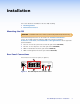
Installation This section details the installation of the GSS 100, including: zz Mounting the GSS zz Rear Panel Connections Mounting the GSS CAUTION: Installation and service must be performed by authorized personnel only. Detailed mounting instructions can be found in the “Reference Information“ section. The 1U high, half-rack width GSS 100 can be placed on a tabletop, mounted on a rack shelf, or mounted under or through furniture. Use the applicable optional hardware: zz RSU 129 9.
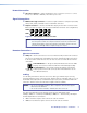
Power Connection a AC power connector — Plug a standard IEC power cord into this connector to connect the GSS to a 100 VAC to 240 VAC, 50 or 60 Hz power source. Signal Connections b RGB Pass-through connectors — Connect a high resolution or computer input (VGA, SVGA, XGA, SXGA, or UXGA) to these female BNC connectors. c Output connectors — Connect an RGB video display or other device to these female BNC connectors (see figure 3 to connect the RGB video format for each configuration).
RJ-45 connector wiring The Ethernet cable can be terminated as a straight-through cable or a crossover cable and must be properly terminated for your application (see figure 4).
Reset Button f Reset button — The Reset button initiates three levels of reset to the GSS. Press and hold the button while the GSS is running or while you power up the GSS for different reset levels. zz Events (mode 3) reset — Hold the Reset button for approximately 3 seconds (the Reset LED blinks once), then release it and push it again for a moment to toggle events monitoring on and off.
Operation This section describes the front panel operation of the GSS 100, including: zz Front Panel Controls and Indicators zz Front Panel Operations Front Panel Controls and Indicators Figure 6 shows the controls and indicators on the front panel of the GSS 100. See “Front Panel Operations” for details on using these controls and indicators. GSS 100 IMAGE MENU TAKE NEXT ADJUST/ SELECT 1 2 3 4 5 6 Figure 6.
Front Panel Operations Plug in all system components and turn on the input device (such as a desktop or laptop computers) and the output monitor. Use the LAN port to upload one or more still images to the GSS. Select either the pass-through input or one of the stored still images to output (see “Selecting an Image to Display”). The image should appear on the monitor connected to the output. Power-on Indications Power is applied when the power cord is connected between the GSS and an AC source.
Selecting an Image to Display NOTES: • The only valid file formats for uploaded image files are BMP and JPG. • Valid file names are up to 240 alphanumeric characters with no spaces. • Progressive JPG images are not supported. • Bitmap (BMP) images must be formatted as 24-bit RGB. • 1080i and 1080p files need to be mastered at a resolution of 1440 x 1080 instead of the expected 1920 x 1080. Select an image to display as follows: 1. Press and release the Image button (see figure 8).
Menu System Overview Figure 10 shows a flowchart of the main menus in the menu system. Power on Extron GSS 100 3 sec. Version n.nn 3 sec. Menu 10 sec. 10 sec. Menu Switch Effect Output Config 10 sec. Menu Slide Show Default Cycle Menu 10 sec. Advanced Menu Menu 10 sec. Menu Next Exit Menu Figure 10. Menu System Flowchart Menu button — Press the Menu button to activate the menu system and to scroll through the five main menus.
Effect submenu Rotate the Adjust/Select knob while in the Effect submenu to cut (immediate switch) and dissolve (the image dissolves from old to new). Cut is the default selection. Duration submenu Rotate the Adjust/Select knob while in the Duration submenu to select the duration for the dissolve effect (if it is selected), between 0.0 and 5.0 seconds in 0.1 second increments. The default duration is 1.0 seconds.
Resolution submenu Rotate the Adjust/Select knob while in the Resolution submenu to select the resolution of the stored image output. 1024 x 768 at 60 Hz is the default resolution. NOTE: To view an uncropped full screen image at 1080p or 1080i, the image resolution must be 1440 x 1080.
Slide Show menu Figure 13 is a flowchart that shows an overview of the Slide Show menu and the available settings. Power on Default Cycle Menu 10 sec. 10 sec. 10 sec. 10 sec. 10 sec. Menu Switch Effect Menu Output Config Menu Slide Show Next Menu 10 sec. Duration Next 030 Secs Menu 10 sec. PassThru Next Disabled Menu Advanced Menu Menu Duration 0 to 300 seconds in 1 second increments Pass-Thru Input • Disabled • Enabled Exit Menu Figure 13.
Advanced menu Figure 14 is a flowchart that shows an overview of the Advanced menu and the available settings. Menu 10 sec. Auto Sw Next Off Default Cycle Power on Menu 10 sec. 10 sec. 10 sec. 10 sec. 10 sec. Menu Menu Name GSS-100- 3 sec. {scroll} Name nn-nn-nn 10 sec. Next Name (Display Only) (Changeable under RS-232/Ethernet control; scrolls to the left if greater than 8 characters.
Name display The read-only Name display shows either the factory default name or a customized name that can be assigned under RS-232 or Ethernet control. If the name is greater than eight characters, the display shows the first eight characters of the assigned name and then scrolls the name to the left to display the remaining characters of the name.
Front Panel Security Lockout (Executive Mode) The front panel security lockout (lock mode 1) limits the operation of the GSS from the front panel. When the GSS is locked, the front panel Menu and Next buttons are disabled, although the Image and Take buttons are still functional. If you push the Menu or Next button when the GSS is locked, the LCD shows X Mode Enabled for approximately 5 seconds and then returns to the default display cycle.
Programming Guide This section describes Simple Instruction Set operation of the GSS 100. The rear panel RS-232 connector (see figure 16) can be connected to the serial port of a host device, such as a computer or control system. Communications with the GSS are via the Extron Simple Instruction Set (SIS). RS-232 5 1 9 6 Pin RS-232 Function 1 — Not used 2 Tx Transmit data 3 Rx Receive data 4 — Not used 5 Gnd Signal ground 6 — Not used 7 — Not used 8 — Not used 9 — Not used Figure 16.
Simple Instruction Set Control Symbols Symbols (values), defined starting below, are used throughout the discussions of the GSS-initiated messages that begin below and the command and response table that begins on page 22. The symbols represent variables in the GSS-initiated messages and the command and response table fields.
X1^ X1& X1* X1( X2) = Event data to write = Number of bytes to read = Pass-through sync status 0 = No sync detected 1 = V sync detected = Bytes of memory used nnnnnnn (bytes) = Firmware version n.nn 2 = H sync detected 3 = HV (composite) sync detected GSS-initiated (Unsolicited) Messages When a local event, such as an equipment power-up, occurs, the GSS responds by sending a message to the host. The GSS-initiated messages are listed in the following pages. The messages are underlined.
Output configuration NOTE: The output configuration settings apply only to the the output of still images stored in the GSS; the RGB pass-through video is output exactly as it is input. RteX%*X^] The GSS 100 initiates the Rte message when a front panel change in the output resolution takes place. SynX&] The GSS 100 initiates the Syn message when a front panel change in the output sync format takes place.
Error Responses When the GSS 100 receives a valid SIS command, it executes the command and sends a response to the host device. If the unit is unable to execute the command because the command is invalid or it contains invalid parameters, the unit returns an error response to the host.
Command and Response Table for SIS Commands Command ASCII Command Response (Host to Unit) (Unit to Host) EX!RF} Cim•X!] Additional description Image recall Recall an image to buffer NOTE: Select image X! to display. It takes several seconds between the issuance of the recall command (EX!RF}) and the receipt of the Cim response. ERF} X!] The buffer is loaded with image X!. % Tke] Swap the displayed and buffered images using the selected effect (cut or dissolve).
Command/Response Table for SIS Commands (continued) Command ASCII Command Response (Host to Unit) (Unit to Host) X%*X^= RteX%*X^] Additional description Output rate Set the output rate NOTE: Set the output resolution for the stored image to X% at X^ Hz. The output rate (=) command affects the display of the stored images only; pass-through sources are output exactly as they are input.
Command/Response Table for SIS Commands (continued) Command ASCII Command Response (Host to Unit) (Unit to Host) Read event buffer memory EX1),X1!,X1@,X1#E} X1$] Read event status EX1)E} X1%] Write event to memory buffer EX1),X1!,X1@,X1^,X1#E} Read string from event buffer memory EX1),X1!,X1@,X1&FE} Write string to event buffer memory EX1^,X1),X1!,X1@FE} Start events Stop events Show # of running events E1AE} E0AE} EAE} Additional description Event (script) control EwrX1),X1^] ]
Command/Response Table for SIS Commands (continued) Command ASCII Command Response (Host to Unit) (Unit to Host) Additional description File management NOTE: A directory name is an alphanumeric text string that can also include the minus (-), plus (+), and colon (:) signs. Blank and space characters are not permitted. The first character must be a letter. The directory name is not case-sensitive.
Command and Response Table for IP- and Port-specific SIS Commands Symbol definitions X4) = Device name NOTE: (Up to 240 alphanumeric characters) The following characters are invalid or not recommended in the name: {space} + ~ , @ = ` [ ] { } < > ‘ “ ” ; : | \ and ?.
Command and Response Table for IP-Specific SIS Commands Command ASCII Command Response (host to unit) (unit to host) Additional description Set device name Read device name Reset device name to factory default Set time and date Read time and date Set GMT offset EX4)CN} ECN} E•CN} Ipn•X4)] X4)] Ipn•X4!] EX4@CT} ECT} EX4$CZ} IptX4@] X4#] IpzX4$] Example: Set Daylight Saving Time Read Daylight Saving Time E8.
HTML Control and IPL File Manager This section describes the operation of the GSS 100, including: zz Configuring the Hardware zz Opening the Embedded Web Pages zz Status Tab zz Configuration Tab zz File Management Tab zz Control Tab zz Images Tab zz Installing the IPL File Manager and Uploading Images zz Special Characters The GSS can be configured through its Ethernet port, connected via a LAN or WAN and using a web browser such as the Microsoft® Internet Explorer®.
Configuring the Hardware To function properly, the controlling PC and the GSS must be configured correctly: the PC must be network capable, with the proper protocols installed, and the hardware configured correctly. The GSS must also be set to recognize and accept commands. PC Configuration This manual assumes that you have a Windows PC equipped with an operating network adapter.
4. Click Start > Run... to activate the Run window. Type Cmd in the Run window and click OK to access the MS-DOS command prompt. 5. Enter the ARP -s command with the desired new IP address (obtained from the system administrator) and the MAC address of the GSS (from the label on the rear panel of the GSS), as follows: C:\> arp -s 10.13.170.15 00-05-A6-00-0A-90 Prompt Command Desired IP address MAC address Enter key 6.
Configuring the GSS using a direct PC connection This type of connection is used to initially connect to and configure the GSS. The default settings of the GSS (IP address, subnet mask, and optional administrator name and password) must be changed in order to use the GSS on an intranet (LAN) or the Internet (WAN). 1. Plug one end of a CAT 5 Ethernet crossover cable into the rear panel LAN port on the GSS. See “Cabling” and “RJ-45 connector wiring” in the Installation section to make a cable. 2.
Opening the Embedded Web Pages Access the GSS 100 using HTML pages as follows: 1. Start the web browser program. 2. Click in the Address field of the browser. 3. Enter the IP address of the GSS in the Address field of the browser. NOTE: If the local system administrators have not changed the value, the factoryspecified default, 192.168.254.254, is the correct value for this field. 4.
Status Tab System Status Page The System Status page (see figure 19) provides an overall view of the status of the GSS 100, including various IP addresses, and the status of the RS-232 port. The System Status page is the default page that the GSS 100 downloads when you connect to the GSS 100. Access the System Status page from other pages by clicking the Status tab. Figure 19. System Status Page The status web page periodically updates itself to reflect the latest status of the GSS 100 components.
Configuration Tab System Settings Page The GSS 100 downloads the System Settings page (see figure 20) when you click the Configuration tab. The screen consists of fields in which you can view and edit IP administration and system settings. You can access the Video Settings, Passwords, and Firmware Upgrade pages by clicking the appropriate link. Refresh Video Settings Passwords No function on GSS Firmware Upgrade Figure 20.
DHCP radio buttons The DHCP On radio button directs the GSS 100 to ignore any entered IP addresses and to obtain its IP address from a Dynamic Host Configuration Protocol (DHCP) server (if the network is DHCP capable). The DHCP Off radio button turns DHCP off. Contact the local system administrator to determine if DHCP is appropriate. NOTE: The IP Address, Gateway IP Address, and Subnet Mask fields become uneditable if DHCP is on.
Date/Time Settings fields The Date/Time Settings fields (see figure 21) provide a location for viewing and setting the time functions. Figure 21. Date/Time Settings Fields Change the date and time settings as follows: 1. Click the drop box for the variable to be changed. The adjustable variables are month, day, year, hours, minutes, AM/PM, and (time) zone. A drop-down scroll box appears (the year drop box is selected in figure 21). 2.
Video Settings Page Access the Video Settings page (see figure 22) by clicking the Video Settings link on the System Settings page. System Settings Refresh Passwords No function on GSS Firmware Upgrade Figure 22. Video Settings Page Set the video settings (resolution, refresh rate, sync format, and sync polarity) and RGB delay as follows: 1. Click the desired field. A drop down scroll box appears (see figure 23). Figure 23.
Passwords Page Access the Passwords page (see figure 24) by clicking the Passwords link on the System Settings page. System Settings Video Settings Refresh No function on GSS Firmware Upgrade Figure 24. Passwords Page The fields on the Passwords page are for entering and verifying administrator and user passwords. Passwords are case sensitive and are limited to 12 uppercase and lowercase alphanumeric characters.
Email Alerts Page The E-Mail Alerts page is an artifact of the HTML pages of other Extron products and has no function for the GSS 100. Future firmware revisions may remove this page. Firmware Upgrade Page The Firmware Upgrade page provides a way to replace the firmware that is coded on the control board of the GSS 100 without taking the GSS 100 out of service. Access the Firmware Upgrade page (see figure 25) by clicking the Firmware Upgrade link on the System Settings page.
6. Click the Firmware Upgrade link (see figure 26). 7 10 8 9 Figure 26. Firmware Upgrade 7. Click the Browse button. A Choose File to Upload window appears. 8. Navigate to the folder where you saved the firmware upgrade file. Select the file. NOTES: • Valid firmware files must have the file extension “.S19.” A file with any other extension is not a firmware upgrade. • The original factory-installed firmware is permanently available on the GSS 100.
File Management Tab File Management Page To delete files such as HTML pages from the GSS 100 or to upload your own files to the GSS 100, click the File Management tab. The GSS 100 downloads the File Management HTML page (see figure 27). Figure 27. File Management Page NOTE: The files listed in figure 27 are shown for example only and may not be present on your GSS 100. To delete a file, click the Delete button associated with that file.
Control Tab Control Page Click the Control tab to access the Control page (see figure 28). Figure 28. Control Page On the Control page, you can set the transition effect (cut or dissolve), mute and unmute the video, and select the dissolve duration (from 0 to 5 seconds, in 0.1-second increments).
Images Tab Image Settings Page Click the Images tab to access the Image Settings page. You can upload and delete stored images and select a stored image for display on the Image Settings page (see figure 29). You can also select the pass-through input for display. The Image Index column displays thumbnails of all stored images in the GSS. The Current Image field identifies the image file that is currently being displayed.
Uploading (adding) an image Upload an image to the GSS 100 as follows: 1. Click the Add button. The Add Image field appears (see figure 30). Figure 30. Uploading an Image 2. Click the Browse button. The Choose File to Upload window appears. 3. Browse through your system and select the desired image file. NOTES: • The only valid file formats for uploaded image files are BMP and JPG. • Valid file names are up to 240 alphanumeric characters with no spaces. • Progressive JPG images are not supported.
Installing the IPL File Manager and Uploading Images You can also upload images using the free Extron IPL File Manager program, designed for the Extron IP Link family of products. You can download the IP Link File Manager software from the Extron website, www.extron.com. Installing the IPL File Manager 1. Log on to the Extron website, www.extron.com. 2. Type IPL file manager in the Search box in the upper-right corner of the web page. Press the keyboard key. 3.
Figure 31. Select Startup Mode Window 3. Type the IP address of the GSS and, if the GSS is password protected, the password into the Add IP Link Interface box. Click OK. 4. The IP Link File Manager program window appears (see figure 32). The window contains two major sections. zz Computer System (left section) — Displays the file system of your computer. In this section you can browse to locate files on your PC hard drive or a server to which you have access.
5. Check to see that the GSS contents include the directory nortxe-graphics. If the “nortxe-graphics“ directory is present in the GSS, proceed to step 6. If the “nortxe-graphics“ directory is not present in the GSS, create the folder as follows: a. Right-click the IP address of the GSS in the IP Link Interfaces (right) section of the window. b. Click Add Directory. c. Type the name nortxe-graphics and then press the key on the PC. 6.
Reference Information This section discusses the specifications, part numbers, and accessories for the GSS 100 Graphic Still Store.
Sync Input type �������������������������������������� Output type ����������������������������������� Input level �������������������������������������� Output level ����������������������������������� Input impedance ���������������������������� Output impedance ������������������������� Max. input voltage ������������������������� Max. propagation delay ������������������ Polarity ������������������������������������������� RGBHV, RGBS RGBHV, RGBS 1.5 V to 5.0 Vp-p TTL: 4.
Control/remote — video processor Serial control port ��������������������������� RS-232, 9-pin female D connector Baud rate and protocol ������������������� 2400 to 115200 baud (configurable) Default settings (adjustable: 9600 baud; 8 data bits; 1 stop bit; no parity Serial control pin configurations ����� 2 = Tx, 3 = Rx, 5 = GND Ethernet control port ���������������������� 1 RJ-45 female connector Ethernet data rate �������������������������� 10/100Base-T, half and full duplex with autodetect Ethernet prot
Part Numbers Item Part Number GSS 100 60-684-01 IEC power cord Rubber feet (4) GSS 100 Setup Guide Mounting Options Part Part Number RSU 129 9.5-inch deep universal rack shelf kit 60-190-01 RSB 129 9.5-inch deep basic rack shelf 60-604-02 MBU 125 Under-desk mount kit 70-077-01 MBD 129 Through-desk mount kit 70-077-02 Cables When using signals with a scanning frequency of 15–125 kHz and running distances of 100 feet (30.
Pre-cut five-conductor cables RG6 BNC Super High Resolution Cables Part Number RG6-5 BNC/3 through BNC/50 (various lengths) 26-369-nn h MHR-5 BNC Mini High Resolution Cable MHR-5 BNC/3 through BNC/100 (various lengths) Part Number 26-260-nn h MHR-5P BNC Plenum Mini High Resolution Cable MHR-5P BNC/3 through BNC/100 (various lengths) Part Number 26-378-nn Mounting the Unit The GSS 100 is housed in a rack-mountable, 1U high, half rack-width metal enclosure.
Furniture Mounting Under-Furniture Mounting Secure an optional MBU 125 under-desk mounting kit brackets (part number 70-077-01) to the unit and mount the unit under a desk or table in accordance with the directions that accompany the kit. Through-furniture mounting Secure an optional MBD 129 through-desk mounting kit brackets (part number 70-077-02) to the unit and mount the unit through a desk or other furniture in accordance with the directions that accompany the kit.
Extron® Warranty Extron Electronics warrants this product against defects in materials and workmanship for a period of three years from the date of purchase.