FPC 5000 Matrix 12800 Switcher Front Panel Controller 68-556-05 Rev.
Precautions Safety Instructions • English This symbol is intended to alert the user of important operating and maintenance (servicing) instructions in the literature provided with the equipment. This symbol is intended to alert the user of the presence of uninsulated dangerous voltage within the product's enclosure that may present a risk of electric shock. Warning Power sources • This equipment should be operated only from the power source indicated on the product.
Table of Contents Chapter 1 • Introduction ....................................................................................................... 1-1 About the Front Panel Controller ............................................................................... 1-2 About the Matrix 12800 System ................................................................................. 1-3 Definitions of Matrix Switcher Terms ......................................................................
Table of Contents, cont’d Admin Screens .................................................................................................................... 3-22 Status screens ................................................................................................................... 3-22 Status screen, System area .......................................................................................... 3-22 Status screen, BME area ...................................................................
FPC 5000 Front Panel Controller 1 Chapter One Introduction About the Front Panel Controller About the Matrix 12800 System Definitions of Matrix Switcher Terms
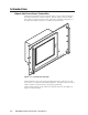
Introduction, cont’d Introduction About the Front Panel Controller The Extron FPC 5000 Front Panel Controller (figure 1-1) is an optional element of the Matrix 12800 family of matrix switchers. The FPC 5000 is a rack-mountable device that provides front panel control of the matrix, including configuration of the inputs and outputs and control of additional system features.
About the Matrix 12800 System The Matrix 12800 system (figure 1-2) is made up of a series of matrix switcher basic module enclosures (BMEs). The family of BMEs allows you to create a video and/ or audio matrix system with up to 128 inputs and 128 outputs specifically tailored to meet your requirements. EXT.
Introduction, cont’d The Matrix 12800 Series includes: • Wideband video switcher BME — A rack-mountable 10U switcher that routes video (red (R), green (G), and blue (B) video planes, component video, S-video, and composite video) from any input to any one or more outputs. • Sync switcher BME — A rack-mountable 10U switcher that routes horizontal (H) and vertical (V) or composite sync from any input to any one or more outputs.
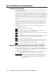
FPC 5000 Front Panel Controller 2 Chapter Two FPC Installation and Operation Installation Overview Unpacking and Assembling the Front Panel Controller Rack Mounting the FPC Assembly Rear Panel Connections Front Panel Features and Operation Upgrading the Software
FPC Installation andand Operation, cont’d FPC Installation Operation Installation Overview The FPC 5000 assembly consists of the FPC computer and a rack-mountable, 7U high, 19” wide metal panel. As part of a complete Matrix 12800 system, the FPC 5000 can be installed in a rack or a cabinet with the rest of the system BMEs. The controller is connected to the Ethernet port of a switching BME.
2. Remove the computer and the panel from the shipping carton. Support the FPC computer as shown in figure 2-1. Figure 2-1 — A properly supported FPC computer and panel 3. Place the computer and panel on the tabletop with a book or other 1”-high object under the computer to support it as it nests in the panel. 4. With the tabs up, angle one of the included mounting blocks and insert the block’s two tabs into the slots on one corner of the FPC computer Tabs (figure 2-2).
FPC Installation and Operation, cont’d 5. Repeat step 4 for each of the remaining three mounting blocks. 6. Thread one of the included 60 mm panhead machine screws into the top of each mounting block. Repeat for the other screws. 7. Tighten the screws until they just contact the rack-mounting panel. Move the panel as necessary to ensure that the four screws contact the panel in the inset holes (figure 2-3). CAUTION Do not overtighten the screws. The screws may bend if overtightened.
Rack Mounting the FPC Assembly The appropriate rack mounting hardware is included with the controller. Rack mount the controller as follows: 1. Insert the controller assembly into the rack, align the holes in the mounting panel with those of the rack. 2. Secure the controller assembly to the rack using the supplied machine screws. Rear Panel Connections NET All connectors are on the rear of the FPC 5000 (figure 2-5). EXT.
FPC Installation and Operation, cont’d For direct connection to BME 0 — Plug the RJ-45 connector on the opposite end of the CAT 5e or higher cable directly into the BME 0 Ethernet port (figure 2-6). Wire the CAT 5e or higher cable as a crossover cable (See Cabling and RJ-45 connector wiring in this chapter). For a multi-BME system, ensure that you connect the FPC to BME 0.
3 Power ( / )switch — Toggle the power switch to the on ( ) position. After approximately 2 minutes, observe that the LCD touch panel displays the FPC start-up screen (figure 2-8). See chapter 3, Matrix 12800 Operation, for using the FPC to operate the Matrix 12800 system.
FPC Installation and Operation, cont’d Cabling and RJ-45 connector wiring It is vital that your cable between the FPC 5000 and the Matrix 12800 BME 0 or LAN be the correct cable, and that it be properly terminated with the correct pinout. This FPC link requires CAT 5e or CAT 6, unshielded twisted pair (UTP) or shielded twisted pair (STP) cables, terminated with RJ-45 connectors. The cable length is limited to 328’ (100 m). Do not use standard telephone cables.
Front Panel Features and Operation Other than the power switch, the remaining control and all of the FPC 5000 indicators are on the front panel (figure 2-10). FPC 5000 2 PWR 3 HDD T/R 4 RESET 5 MATRIX SWICHER CONTROLLER 1 Figure 2-10 — Front panel control and indicators 1 LCD touch panel — The LCD panel displays front panel controller screens. The touch panel responds to selections that the operator makes by touching the screen.
FPC Installation and Operation, cont’d Upgrading the Software The Front Panel Controller software is factory installed on the FPC computer’s hard drive and it is also included on a CD-ROM. Extron sends any needed software upgrades on a CD-ROM. Upgrade the FPC software as follows: 1. If necessary, log the FPC 5000 on to the Matrix 12800 system as an administrator. See Starting Up the Controller and Logging In and Out in chapter 3, Matrix 12800 Operation. 2.
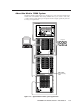
On the rear of the FPC, support the CD tray from behind with one hand while you snap the program CD onto the tray spindle with the unlabeled (program) side of the CD facing into the tray (figure 2-12). EXT. FDD K/B MOUSE NET 6. CO C PR M3 CO M2 CO 4 OM N DIO -2 100V AC T INPU 30V Figure 2-12 — Inserting the program CD into the CD tray 7. On the rear of the FPC, gently push the CD tray back into the FPC computer until it locks in place. 8. On the front panel, touch on the gray OK button.
FPC Installation and Operation, cont’d 2-12 FPC 5000 Front Panel Controller • FPC Installation and Operation
FPC 5000 Front Panel Controller 3 Chapter Three Matrix 12800 Operation Introduction Operating the Touch Panel Starting Up the Controller and Logging In and Out Demo Mode Navigating the Screens User Screens Admin Screens Setup Screens Subnetting — A Primer
Matrix 12800 Operation, cont’d Matrix 12800 Operation Introduction This chapter details operation of a Matrix 12800 system using an FPC 5000 front panel controller. The chapter assumes that the Matrix 12800 is properly installed, virtualized, and operating correctly.
• To dismiss the on-screen keyboard without entering the typed in characters, touch the Cancel key. Using the keypads An on-screen keypad (figure 3-2) is integrated into the I/O screens. A similar keypad is available from the TCP/IP screens and appears when you take a step that requires that you enter numeric characters. I/O Keypad TCP/IP Keypad Figure 3-2 — I/O and TCP/IP on-screen keypads , if present, • For the I/O keypad, touch the keypad's yellow Clear button to clear the keypad display.
Matrix 12800 Operation, cont’d Starting Up the Controller and Logging In and Out Use the FPC to control the matrix as follows: 1. Ensure that all BMEs that are part of the system have been connected to each other and their BME numbers have been set correctly (refer to the Matrix 12800 Wideband, Sync, or Audio Switchers User’s Manual, part #68-556-01). 2. If necessary, on the rear of the FPC, toggle the Power switch to the on ( ) position.
To log on to the Matrix 12800, the FPC 5000’s IP address and Subnet Mask fields must be set to values that identify them as being on the same subnet as the Matrix 12800 BME 0. See Subnetting — A Primer at the end of this chapter.
Matrix 12800 Operation, cont’d If the local system administrators have not changed the value, the factoryspecified default, 192.168.254.253, is the correct value for this field. d. If you want to use the factory defaults, touch the Use Factory Defaults button and proceed to step 5l. e. Touch the IP Address field. The on-screen numeric keypad appears (figure 3-2). f. Enter the IP address. Invalid IP addresses are displayed in red. g.
c. Touch the on-screen keyboard's Enter key to accept the password and dismiss the keyboard from the display. The FPC software looks for the Touch the Connect button. Matrix 12800 system and reads its hardware configuration: the type and size of each BME. The software then reads all of the current settings, such as the ties, presets, and virtual map. Observe the message LoggedOn as ADMINISTRATOR (or USER) in the upper right corner of the blue field. 8.
Matrix 12800 Operation, cont’d User Screens Preset Screens Global Preset Screen Room Preset Screen DSVP Screen Mute Screen View and Make Ties Screens View Input Ties by Output Screen View Input Ties Alternate Screen View Output Ties Alternate Screen View Output Ties by Input Screen Make Ties Alternate Screen Make Ties Screen User Screens Adminstration Screens Setup Screens Administration Screens See figure 3-7b Setup Screens See figure 3-7b Figure 3-7a — FPC 5000 Startup screen and menu flowchart
User Screens See figure 3-7a Administration Screens TCP/IP Screen E-mail Screen User Screens Adminstration Screens Status Screen Miscellaneous Screen Setup Screens Setup Screens Audio Screen Reset Screen Delay Screen Figure 3-7b — FPC 5000 Startup screen and menu flowchart (part 2) FPC 5000 Front Panel Controller • Matrix 12800 Operation 3-9
Matrix 12800 Operation, cont’d In the following procedures, access to a specific screen is described by assuming you are beginning at the startup screen and listing the color of the buttons and their displayed message, in order, separated by a > symbol. For example, to access the Make Ties screen, touch the blue User > amber I/O > green Make Ties buttons. The button progression lists all buttons that may be necessary to access a specific screen.
Figure 3-8 — View ties screens flowchart FPC 5000 Front Panel Controller • Matrix 12800 Operation 3-11 2 ViewTies: outputs-by-input selection screen 3 ViewTies: input-by-output alternate screen 4 ViewTies: outputs-by-input alternate screen When you touch the green View Outputs/View Inputs selection button on the screen, the FPC toggles between the two View Ties screens.
Matrix 12800 Operation, cont’d View the ties as follows: 1a. From any screen other than the Make Ties Screen, touch the blue User > amber I/O buttons. 1b. From the Make Ties screen, touch the green View Ties button. The FPC displays one of the View Ties screens. The screen view that the FPC displays is the last View Ties screen that was active. 2. To select the View Ties: input-by-output-selection screen, touch the green View Inputs button. 3.
Viewing outputs tied to a specified input View the output tied to a selected input as follows: 1. If necessary, touch the View Outputs button. The most recently selected View Ties: output-by-input-selection screen appears. See 2 and on figure 3-8. to display screen 2. If necessary, touch the Change View button figure 3-8. 3. Select the video and/or audio format(s) to view by touching the desired blue Signal Type button(s).
Matrix 12800 Operation, cont’d Creating ties There are two ways to make ties (figure 3-9): • You can select an input and an individual output on the Make Ties: dual keypad screen ( 5 ). • You can select and input and then select one or a group of outputs on the Make Ties: alternate view screen ( 6 ). You can make ties or groups of ties individually, on the fly, or create a series (queue) of potential ties or groups of ties to switch all at once.
Tie an input to an output as follows: 1. Touch the blue User > amber I/O > green Make Ties buttons. The FPC displays one of the I/O Make Ties screen (figure 3-9). The screen view that the FPC displays is the last Make Ties screen that was active. 2. Select the video and/or audio format(s) to tie by touching the desired Signal Type button(s). On the dual-keypad screen, the first virtual output among the selected signal types is displayed in the Virtual Output field.
Matrix 12800 Operation, cont’d 5. To add the potential tie that you have just created to a queue of tie commands that take affect all at once, touch the green Queue button. The FPC displays the equivalent SIS commands in the Pending Tie commands field. The example above shows a queue of SIS commands for tieing input 11 to output 11, input 2 to output 2, input 3 to output 4, and input 4 to output 3.
5. To add the potential tie or set of ties that you have just created to a queue of tie commands that take affect all at once, touch the green Queue button. The FPC displays the equivalent SIS commands in the Pending Tie commands field. To add more potential ties to the queue, repeat steps 1 through 3. 6. Only one input can be tied to given output.
Matrix 12800 Operation, cont’d 3. Touch the green Save, Recall, or Delete button. stores the current configuration in memory. If the global preset you selected was previously unassigned, the name in the preset button changes to “Preset nnn”. retrieves the configuration to be the current configuration. clears the configuration information and clears the preset name. 7 Global Presets screen On the Gobal Preset screen, this button reads Room and selects the Room Preset screen when touched.
Save, recall, or delete a room preset See 8 on figure 3-10. Save, recall, or delete a room preset as follows: Touch the blue User > amber Preset > green Room buttons. 1. The FPC displays the Room Preset screen. 2. Select the room to which the desired preset is or will be assigned by touching the desired room button. 3. Select the desired room preset number by touching the appropriate preset button. The Delete, Save, and Recall buttons appear.
Matrix 12800 Operation, cont’d Mute screen The Mute screen (figure 3-11) lets you mute the audio or RGBHV or RGBS video (black screen) for an individual virtual output or all virtual outputs. Access the Mute screen by touching the blue User > amber Mute buttons. Figure 3-11 — Mute screen Touch the RGB or Audio box for an output in order to toggle the video or audio mute for that virtual output on or off.
DSVP screen You can monitor each RGBHV and RGBS input to see if active sync signal(s) are present on the DSVP™ (Digital Sync Validation Processing™) screen (figure 3-12). Access the DSVP screen by touching the blue User > amber DSVP buttons. Figure 3-12 — DSVP screen Where an input has active sync present, the DSVP screen reports a snapshot in time of the frequencies in the horizontal and vertical frequency fields.
Matrix 12800 Operation, cont’d Admin Screens The Admin family of screens include the functions that are typically reserved for or applicable to maintenance personnel only. The family consists of the Status screen (the default), the TCP/IP screen, the E-mail screen, and the Miscellaneous screen. Status screen The Status screen (figure 3-13) provides a snapshot in time of the status of the complete Matrix switcher system, encompassing all BMEs and their active replaceable components.
Status screen, BME area The BME area of the Status screen shows more detailed status for a specific, selected, BME. BME 0 is the default display. To select another BME for display, touch the gray BME button in the System area. Selecting another BME does not update the System status area, it only changes the focus of the BME area.
Matrix 12800 Operation, cont’d TCP/IP screen The TCP/IP screen (figure 3-15) consists of fields from which administrators can observe and edit IP administration and system settings. Figure 3-15 — TCP/IP screen There are two levels of FPC 5000 password protection: administrator and user. Administrators have full access to all Matrix 12800 editing functions. Users cannot change any settings on the TCP/IP screen.
Password fields Only personnel logged in as administrators can set and read passwords. The two Password fields on the TCP/IP screen are for entering administrator and/or user passwords. Passwords are case sensitive and are limited to 12 upper case and/or lower case alphanumeric characters. When logged on as a user, characters in these fields are masked by asterisks (*****) and are not editable. If you do not want to password protect an access level, leave the associated Password field blank.
Matrix 12800 Operation, cont’d Subnet Mask field Only personnel logged in as administrators can edit the Subnet Mask field. The Subnet Mask field is used to determine whether the Matrix 12800 is on the same subnet as the mail server when you are subnetting. See Subnetting — A Primer, at the end of this chapter, for more information on the Subnet Mask field and its contents. FPC IP Address field The FPC IP Address field contains the IP address of the FPC computer.
4. To change the e-mail notification settings, use a pencil eraser or other small, soft, object to touch the round radio buttons and square check boxes. A 5. or appears when an item is selected. Touch the green Take button Cancel button to accept the changes or touch the green to reject the changes. Mail Server IP Address field Only personnel logged in as administrators can edit the Mail Server IP Address field.
Matrix 12800 Operation, cont’d Miscellaneous screen The Miscellaneous screen (figure 3-17) provides the pathway to a series of functions that are not easily categorized elsewhere, such as a file manager, function key programming, the I/O connectors, the screen saver, touch screen calibration, and updating the software. Access the Miscellaneous screen by touching the blue Admin > purple Misc buttons.
File Manager screen The File Manager screen (figure 3-18) is a reference screen only, with no active functions. The screen displays the user-supplied files that have been downloaded into the Matrix 12800 BME 0 to support user-created web pages. Access the File Manager screen by touching the blue Admin > purple Misc > gray File Manager buttons. Figure 3-18 — File Manager screen - files shown are for example only This screen displays the contents only; files cannot be uploaded or deleted.
Matrix 12800 Operation, cont’d Function Keys screen Only personnel logged in as administrators can set User Function keys. The Function Keys screen (figure 3-19) lets you program an SIS command or a series of commands (a macro) to the 14 white/purple User Function buttons or to edit the button assignment. The User Function buttons are always present on the left side of the screen. It is not the function of this manual to define the Matrix 12800 SIS commands.
5. Use a pencil eraser or other small, soft, object to touch the None, Momentary, or Toggle radio button to select that how the User Function button functions. appears in the radio button when it is selected. None — The User Function button is not active. The none function is helpful to mask commands that you want available when needed but that you can disable when not needed, such as a reset. To make a none function, you must select momentary or toggle, enter the command, and then select none.
Matrix 12800 Operation, cont’d I/O Physical Connectors screen The I/O Physical Connectors screen (figure 3-20) shows how the Matrix 12800 system is virtualized. The screen shows the virtual numbers, names, signal types, video and audio planes, and physical connectors associated with the inputs and outputs. The screen also provides the tools to name virtual input and outputs.
Naming inputs and outputs Only personnel logged in as administrators can name video and audio inputs and outputs. Change the input or output name from the I/O Physical Connectors screen as follows: 1. Use the slide bar to scroll through the valid inputs or outputs until the screen displays the virtual input or virtual output you wish to name. 3. Touch the Name field of the virtual input or output name that you wish to edit. The on-screen keyboard appears. 4.
Matrix 12800 Operation, cont’d Delay screen Only personnel logged in as administrators can set the RGB delay. The Delay screen (figure 3-21) displays and provides controls to adjust the RGB delay for RGBHV or RGBS video. With RGB delay, the Matrix 12800 switches to the new sync signal before switching RGB (video) signals. This allows a brief delay for the displays to adjust to the new sync timing before displaying the new picture, which then appears without glitches.
Audio screen Only personnel logged in as administrators can set the audio level. The audio level of each input can be displayed and adjusted through a range of -24dB to +9dB to ensure that there is no noticeable volume difference among sources. The Audio screen (figure 3-22) displays and provides controls to adjust each input’s audio level. Figure 3-22 — Audio screen Access the Audio screen by touching the blue Setup > cyan Audio buttons.
Matrix 12800 Operation, cont’d Reset screen Personnel logged in as users can reset all current ties and all mutes. All other selections are reserved for administrators only. The Reset screen (figure 3-23) provides several different Matrix 12800 reset functions, that allow you to clear specific areas of the switcher. Figure 3-23 — Reset screen Access the Reset screen by touching the blue Setup > cyan Reset buttons.
Subnetting — A Primer It is not the purpose of this manual to describe TCP/IP protocol in detail. However, some understanding of TCP/IP subnetting (subset of a network) is necessary in order to understand the interaction of the Matrix 12800 system components (consisting of the Matrix 12800 and the FPC 5000) and the system’s interaction with the mail server gateway.
Matrix 12800 Operation, cont’d 3-38 FPC 5000 Front Panel Controller • Matrix 12800 Operation
Extron’s Warranty Extron Electronics warrants this product against defects in materials and workmanship for a period of three years from the date of purchase.
www.extron.com Extron Electronics, USA Extron Electronics, Europe Extron Electronics, Asia Extron Electronics, Japan 1230 South Lewis Street Anaheim, CA 92805 USA 714.491.1500 Fax 714.491.1517 Beeldschermweg 6C 3821 AH Amersfoort The Netherlands +31.33.453.4040 Fax +31.33.453.4050 135 Joo Seng Road, #04-01 PM Industrial Building Singapore 368363 +65.6383.4400 Fax +65.6383.4664 Daisan DMJ Building 6F 3-9-1 Kudan Minami Chiyoda-ku, Tokyo 102-0074 Japan +81.3.3511.7655 Fax +81.3.3511.