
User Guide Owner manual

Receiver Connections, Controls, and Indicators
Rear panel
12V
1.0A MAX
POWER
LINK
OPTICAL
RxTx
LINK
HDMI AUDIO
HDMI
AUDIO
OUTPUTS
OFF
ON
REMOTE
RS-232
Tx Rx
RS-232
OVER FIBER
ALARM
Tx Rx 1 2
LR
FOXBOX Rx HDMI
17
1413 1219 15 1816
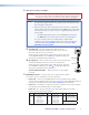
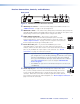
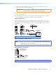
Figure 4. FOXBOX Rx Receiver Rear Panel Features
l HDMI Output connector — Connect a video display to this HDMI connector. See
“HDMI connector“ on page 12 for pin assignments.
m HDMI Audio switch — This switch mutes (Off position) and unmutes (On position) the
embedded audio output on the HDMI output connector. The audio on the captive screw
output always remains active regardless of the setting of this switch.
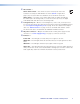
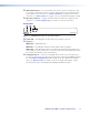
n Audio output connector — This 5-pole, 3.5 mm captive
LR
AUDIO
screw connector outputs the transmitted, unamplified, line level audio.
Connect audio devices, such as an audio amplifier or powered speakers. See
“Audio output connector“ on page 14 to wire a captive screw connector
for the appropriate output type and impedance level.
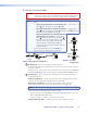
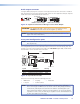
o RS-232 Over Fiber port — If you want the FOXBOX to pass serial
ALARM
Tx Rx 1 2
RS-232
OVER FIBER
command signals to a slave device, for serial control of a projector for
example, connect the slave device to the receiver via the first three leftmost
poles (Tx, Rx, and
_
) of this 5-pole captive screw connector. See “RS-232
connections“ on page 13 to wire this connector.
NOTES: • If you connect only one fiber optic cable (item
q
, on the next page), or
you configure the receiver for daisy-chaining, you will not receive reports
from the controlled device. To receive responses from the controlled
device, you must install two fiber optic cables and leave link 2 enabled
(via an SIS command to the receiver or using the FOX Extenders
Control Program).
• The FOXBOX can pass RS-232 commands and responses at rates up to
115200 baud.
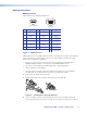
p Alarm outputs port — For remote monitoring of the status of fiber optic
ALARM
Tx Rx 1 2
RS-232
OVER FIBER
link 1, connect a locally-constructed or furnished monitoring device to the
receiver via the two rightmost poles (1 and 2) of this 5-pole captive screw
connector. When the receiver does not detect a light link on fiber cable Rx,
pin 1 and pin 2 of this port are shorted together (see “Alarm outputs connection“ on
page 13 to wire this connector).
FOXBOX Tx/Rx HDMI • Installation and Operation 9